
A kind of urea tank and its cover for scr post-processing system

A technology of urea tank and tank cover, which is applied in the direction of exhaust gas treatment, arrangement combined with internal combustion engine fuel supply, separation method, etc., which can solve the problem of limited ventilation capacity of waterproof and breathable membrane, easy blowout of waterproof and breathable membrane, failure of ventilation function, etc. question

Active Publication Date: 2022-07-15
WEICHAI POWER CO LTD +1
View PDF0 Cites 0 Cited by
  • Summary
  • Abstract
  • Description
  • Claims
  • Application Information

AI Technical Summary

Problems solved by technology

[0004] However, the ventilation capacity of the waterproof and breathable membrane is limited, and the air pressure and air flow of the air-assisted urea pump are relatively large when it is powered off and blown back, so the waterproof and breathable membrane is easy to be blown, and then loses the dustproof function
In addition, when outside rain or water accidentally enters the tank cover, the waterproof and breathable membrane is easily submerged and blocked, which leads to the failure of the ventilation function. Therefore, when the urea pump sucks urea from the urea tank, the suction resistance of the urea pump increases and the pressure builds up. Difficult, the urea tank is sucked flat, or even ruptured; when the (air-assisted) urea pump is turned off and powered back, the high-pressure air delivered to the urea tank cannot be discharged in time, causing the urea tank to bulge and rupture

Method used


Image

  • A kind of urea tank and its cover for scr post-processing system
  • A kind of urea tank and its cover for scr post-processing system
  • A kind of urea tank and its cover for scr post-processing system

Examples


Embodiment Construction

[0031] For ease of understanding, the present invention will be further described below with reference to the accompanying drawings.

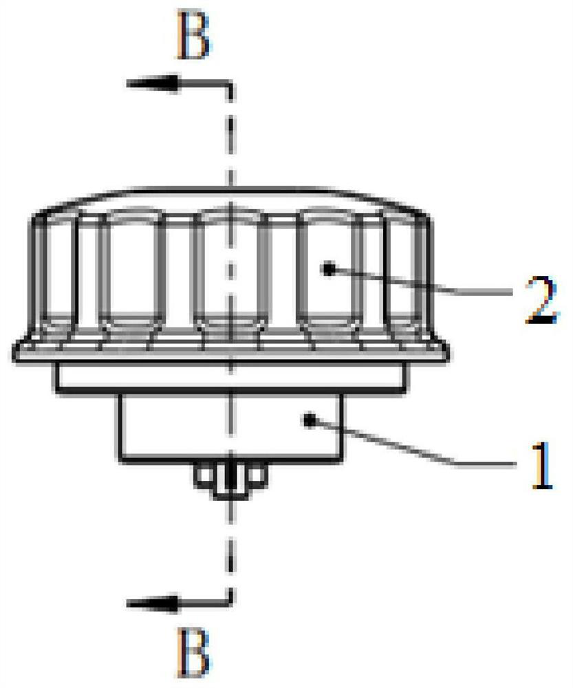
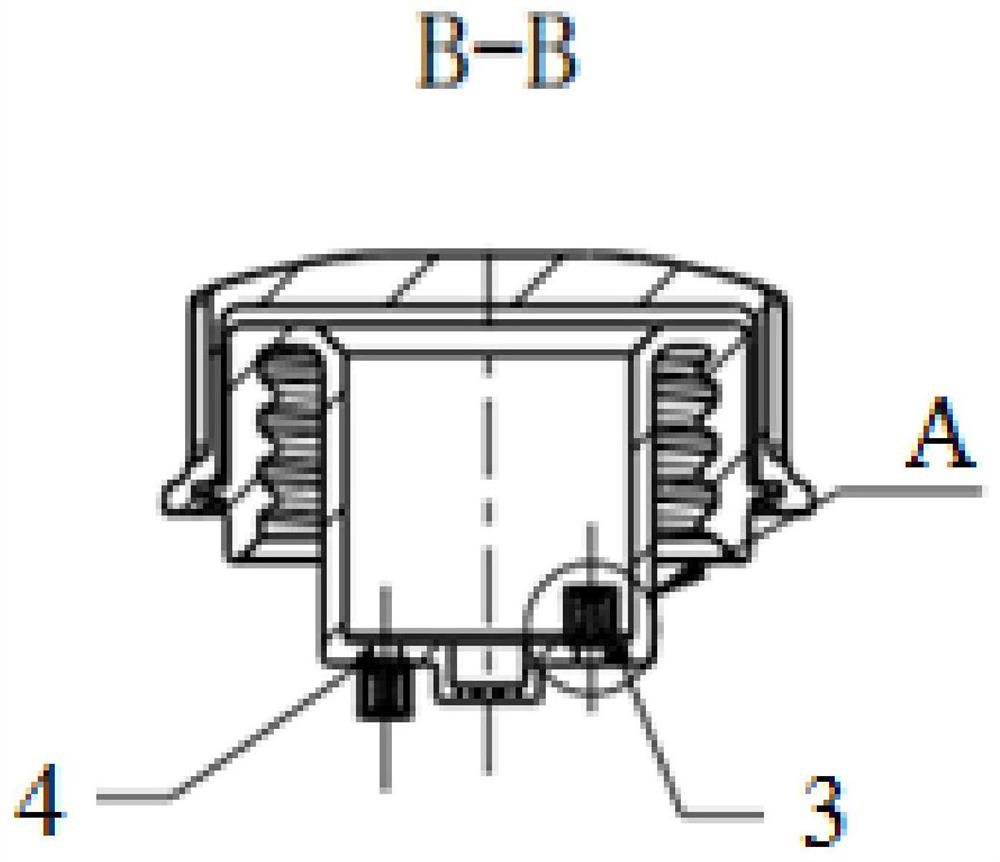
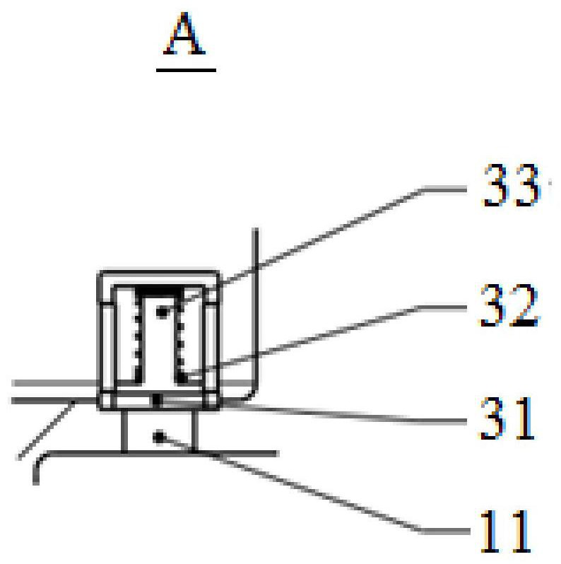
[0032] see Figure 1 to Figure 4 , figure 1 is a schematic diagram of a tank cover of a urea tank used in an SCR post-treatment system provided by an embodiment of the present invention, figure 2 Yes figure 1 B-B sectional view in, image 3 Yes figure 2 The enlarged view at A, Figure 4 Yes figure 1 bottom view.

[0033] The tank cover provided in the embodiment of the present invention is installed at the liquid injection port of the tank body of the urea tank, and the part of the tank cover corresponding to the liquid injection port is provided with ventilation holes, and the ventilation holes are covered by a waterproof and breathable film 5, such as Figure 4 shown. At the same time, the part of the tank cover corresponding to the liquid injection port is also provided with an air intake hole (not marked in the figure) and an exha...


PUM


Abstract

The invention provides a urea tank and its cover for an SCR post-treatment system. The cover is installed at the liquid injection port of the tank body of the urea tank, and the part of the tank cover corresponding to the liquid injection port is provided with ventilation holes. , the ventilation hole is covered by a waterproof and breathable membrane (5), the part of the box cover corresponding to the liquid injection port is also provided with an air intake hole and an exhaust hole (11), and a first constant pressure check valve (3) is installed on the box cover. ) and the second constant pressure check valve (4), the inlet of the first constant pressure check valve (3) is connected to the exhaust hole (11), and the outlet of the first constant pressure check valve (3) is connected to the outlet of the box. The outside is communicated, the inlet of the second constant pressure check valve (4) is butted with the air inlet hole, and the outlet of the second constant pressure check valve (4) is communicated with the inside of the box. After the box cover provided by the invention is adopted, the inner pressure and the outer pressure of the box body will not be seriously unbalanced due to the insufficient air permeability of the waterproof breathable membrane, so the occurrence of deflated deformation or bulging deformation can be effectively avoided, and the urea tank is safer ,reliable.

Description

technical field [0001] The invention relates to the technical field of diesel engines, in particular to a urea tank and a tank cover thereof used in an SCR aftertreatment system. Background technique [0002] Now the regulations on automobile emissions are becoming more and more stringent, and higher requirements are constantly being put forward on the aftertreatment of automobile exhaust. SCR catalytic reduction technology is an important technical route to reduce NOx emissions from diesel engines and meet national IV and above emission regulations. [0003] The SCR post-processing system includes a urea aqueous solution storage device, called a urea tank. The urea tank is mainly composed of a tank body, a tank cover and a sensor. The urea tank needs to have a ventilation function to ensure the balance of pressure inside and outside the tank, usually through the tank cover. It is realized by punching holes on the top. In order to prevent dust from entering the urea tank th...

Claims


Application Information

Patent Timeline
IPC IPC(8): F01N3/28B01D53/94
CPCF01N3/2066F01N2610/1406F01N2610/1413F01N2610/148F01N2610/1446F01N13/16B01D2251/2067B01D53/90F01N2610/02B60K15/04Y02A50/20Y02T10/12B01D53/9418B01D53/9431F01N2610/1466B60K15/03
Inventor 王瑞于佳
Owner WEICHAI POWER CO LTD
Learn More