
Vertical end face scratch-free grinding device

A grinding and end face technology, applied in the field of bearing processing, can solve the problems of workpiece scratches, low machining stability, end face scratches, etc., and achieve the effect of avoiding scratches and high finish.

Pending Publication Date: 2020-11-24
南通山口精工机电有限公司
View PDF0 Cites 0 Cited by
  • Summary
  • Abstract
  • Description
  • Claims
  • Application Information

AI Technical Summary

Problems solved by technology

[0002] The end faces of both sides of the inner and outer rings of the bearing have precision requirements. Generally, the end faces are ground by a double-end grinder. Usually, the machine tool is adjusted to have a large inlet and a small outlet, so that the workpiece is gradually ground. However, this is what causes the workpiece to be scratched. The root cause is that the small outlet of the feeder makes the workpiece still be ground before leaving the grinding wheel. There is no smooth grinding time. When the workpiece leaves the grinding wheel, it is easy to cause various scratches, especially the production of ultra-miniature bearing products. The characteristics of thin, small, fine, micro and contact plane are too small, the processing stability is relatively low, resulting in end surface scratches > 5%

Method used


Image

  • Vertical end face scratch-free grinding device
  • Vertical end face scratch-free grinding device
  • Vertical end face scratch-free grinding device

Examples


Embodiment Construction

[0015] The technical solutions in the embodiments of the present invention will be clearly and completely described below.

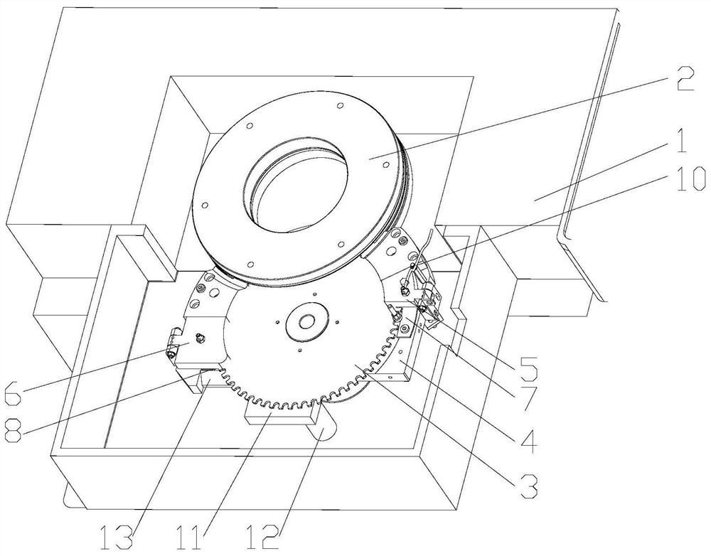
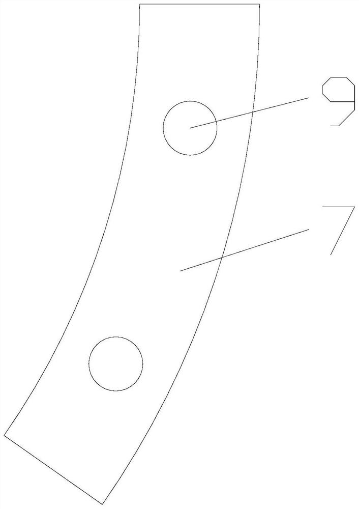
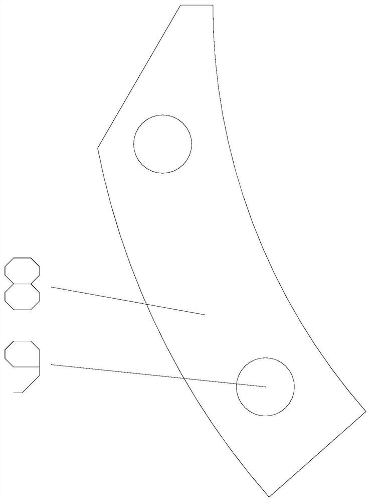
[0016] Such as Figure 1~3 As shown, the vertical end surface scratch-free grinding device is processed by Koyo KVD300 double-end surface grinding machine. There is a frame 1 in the grinding machine, and the double-layer grinding wheel 2 is rotatably connected to the frame 1. The double-layer grinding wheel The grinding gap between the 2 can be adjusted in the grinding machine; a feed tray 3 is arranged to rotate between the double-layer grinding wheels 2, and a motor is installed at the bottom of the frame 1, and the motor drives the feed tray 3 to rotate; the feed tray 3. The bottom is connected with a tray 4; the two sides of the tray 4 are respectively provided with a feed plate 5 and a discharge plate 6, and the ends of the feed plate 5 and the discharge plate 6 are connected to the tray through a pin rotation 4 side; after the feed plate 5 is turn...


PUM


Abstract

The invention discloses a vertical end face scratch-free grinding device. The device comprises a rack, double layers of grinding wheels are rotationally connected to the rack, a feeding disc is rotationally arranged between the double layers of grinding wheels, and a material supporting disc is connected to the bottom of the feeding disc; a feeding plate and a discharging plate are arranged on thetwo sides of the material supporting disc respectively, a feeding channel is formed between the feeding plate and the material supporting disc, and a discharging channel is formed between the discharging plate and the material supporting disc; a first gasket is arranged in the feeding channel, and a second gasket is arranged in the discharging channel; and one end of the first gasket and one endof the second gasket extend into the double-layer grinding wheel. Compared with the prior art, the vertical type end face scratch-free grinding device has the advantages that a machining channel statewith a small inlet and a large outlet is formed through the first gasket and the second gasket, more allowance of a workpiece is ground at the inlet, the grinding amount is small at the position close to the outlet, and the light grinding effect is achieved; and the workpiece is enabled to obtain higher smoothness, so that the workpiece is effectively prevented from being scratched.

Description

technical field [0001] The invention relates to the technical field of bearing processing, in particular to a vertical end face scratch-free grinding device. Background technique [0002] The end faces of both sides of the inner and outer rings of the bearing have precision requirements. Generally, the end faces are ground by a double-end grinder. Usually, the machine tool is adjusted to have a large inlet and a small outlet, so that the workpiece is gradually ground. However, this is what causes the workpiece to be scratched. The root cause is that the small outlet of the feeder makes the workpiece still be ground before leaving the grinding wheel. There is no smooth grinding time. When the workpiece leaves the grinding wheel, it is easy to cause various scratches, especially the production of ultra-miniature bearing products. Due to the product itself The characteristics of thin, small, fine, micro and contact plane are too small, the processing stability is relatively low...

Claims


Application Information

Patent Timeline
Patent Type & Authority Applications(China)
IPC IPC(8): B24B7/17B24B27/00B24B47/20
CPCB24B7/17B24B27/0069B24B27/0076B24B27/0084B24B47/20
Inventor 徐境福周威陈怀宇
Owner 南通山口精工机电有限公司
Learn More