

Control device for airplane braking
A control device and aircraft technology, applied in the direction of aircraft brake arrangement, brake transmission device, brake, etc., can solve the problems of the driver's handling complaints, affecting the safe landing of the aircraft, and difficulty in braking and turning, so as to improve anti-interference, Conducive to flight safety and ensure effective execution
- Summary
- Abstract
- Description
- Claims
- Application Information
AI Technical Summary
Problems solved by technology
Method used
Image

Examples
Embodiment Construction
[0030] In order to make the purpose, technical solution and advantages of the present invention more clear, the embodiments of the present invention will be described in detail below in conjunction with the accompanying drawings. It should be noted that, in the case of no conflict, the embodiments in the present application and the features in the embodiments can be combined arbitrarily with each other.
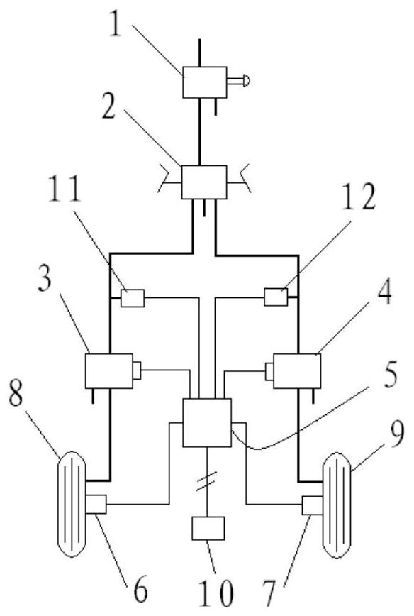
[0031] The operating mode of the aircraft braking device shown in this embodiment is an aircraft braking system with hand brake and foot differential. like figure 1 As shown, the aircraft brake device includes a hydraulic brake valve 1 and a brake distribution valve 2, the hydraulic brake valve 1 is used to start the brake, sends a brake command to the wheel brake device and provides brake pressure, and the brake distribution valve 2 is used to control the braking after the brake is activated. Aircraft directional brake correction and aircraft taxiing ground turn. The oil i...
PUM
 Abstract
Description
Claims
Application Information