Stope drilling device and method for open-pit mining

A drilling device and open-pit mining technology, applied in drilling equipment and methods, ground mining, underground mining, etc., can solve the problems of inability to drill in multiple directions in the stope, inconveniently changing the angle of drilling, and increasing labor costs. Achieve the effect of increasing labor cost, improving service life and good effect

Inactive Publication Date: 2020-11-24
韦秀妃
View PDF0 Cites 9 Cited by
  • Summary
  • Abstract
  • Description
  • Claims
  • Application Information

AI Technical Summary

Problems solved by technology

[0003] The object of the present invention is to provide a stope drilling device and method for open-pit mining, to solve the problem that the current stope drilling device proposed in the above background technology is not convenient to change the angle of the drilling, resulting in the inability to carry out multi-direc

Method used


Image

  • Stope drilling device and method for open-pit mining
  • Stope drilling device and method for open-pit mining
  • Stope drilling device and method for open-pit mining

Examples


Embodiment 1

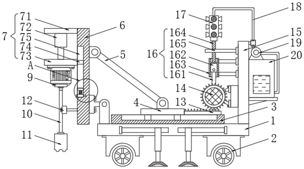
[0029] The present invention provides a technical solution: a stope drilling device for open-pit mining, please refer to figure 1 , comprising a transport vehicle body 1, wheels 2 are installed around the bottom of the transport vehicle body 1, the top of the transport vehicle body 1 is fixedly connected with a fixed plate 3, and the top of the fixed plate 3 is slidably equipped with a movable plate 4, and the movable plate 4 The top is hinged with one end of the pull rod 5, the other end of the pull rod 5 is hinged on the fixed beam 6, the right bottom of the fixed beam 6 is hinged with the transport vehicle body 1 through a hinge, and the left side of the fixed beam 6 is equipped with a height adjustment assembly 7, The height adjustment assembly 7 is connected with a protection assembly 8, and the height adjustment assembly 7 is equipped with a drilling motor 9. The drilling motor 9 is controlled by an external power switch, and the drilling motor 9 is connected to an extern...

Embodiment 2

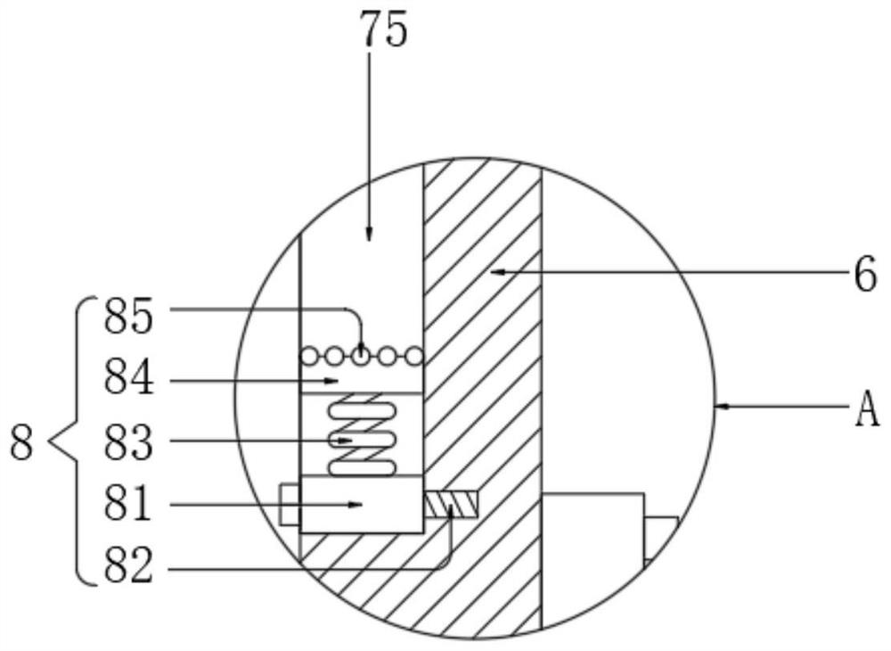
[0038] see figure 2 The difference from Embodiment 1 is that the protection assembly 8 includes a connection block 81 that is movably connected to the bottom of the chute 75, the inside of the connection block 81 traverses through the limit bolt 82, and the right end of the limit bolt 82 is connected to the fixed beam 6, By pulling down the limit bolt 82, the connection block 81 can be replaced, and then the support spring 83 can be replaced. The top of the connection block 81 is connected with the support spring 83, and the top of the support spring 83 is connected to the protection block 84, and the protection block 84 is slidably connected to the chute 75, the top of the protection block 84 is evenly embedded with rubber balls 85, when the slide block 74 moves down and is pressed against the protection block 84, the rubber ball 85 and the support spring 83 are elastically deformed, so that the slide block 74 will not hit To the bottom of the chute 75, the damage of the sli...


PUM


Abstract

The invention discloses a stope drilling device and method for open-pit mining in the technical field of stope open-pit mining. The stope drilling device comprises a transport vehicle body; wheels areinstalled on the periphery of the bottom of the transport vehicle body, a fixed plate is fixedly connected with the top of the transport vehicle body, and a movable plate is installed on the top of the fixed plate in a sliding mode; the top of the movable plate is hinged to one end of a pull rod, and the other end of the pull rod is hinged to a fixed beam; the bottom of the right side of the fixed beam is hinged to the transport vehicle body through a hinge part; and a height adjusting assembly is installed on the left side of the fixed beam. A hydraulic cylinder continues to drive a drill rod to move upwards, and a drilling motor drives the drill rod to rotate, so that a mud scraping rod can scrape off mud attached to the drill rod; and a reset spring enables a movable block to drive a connecting rod to extrude a push plate through the elasticity of the reset spring, moreover, the push plate is extruded through the elasticity of a stress spring, so that the mud scraping rod is more tightly attached to the drill rod, and the mud scraping effect is better.

Description

technical field [0001] The invention relates to the technical field of stope open-pit mining, in particular to a stope drilling device and method for open-pit mining. Background technique [0002] In the process of mining, it is necessary to drill first and then mine. The current stope drilling device is inconvenient to change the angle of the drill hole, resulting in the inability to perform multi-directional drilling in the stope, and because the drill pipe is reused during drilling, There will be a lot of soil attached to the drill pipe, which will easily cause the drill pipe to rust for a long time. After each drilling, manual cleaning will greatly increase the labor cost. Therefore, we propose a mining method for open-pit mining. Field drilling apparatus and method. Contents of the invention [0003] The object of the present invention is to provide a stope drilling device and method for open-pit mining, to solve the problem that the current stope drilling device pro...

Claims


Application Information

Patent Timeline
IPC IPC(8): E21C41/30E21B3/02E21B7/02E21B7/04E21B12/00E21B12/06E21B15/00E21B15/04E21B21/00
CPCE21B3/02E21B7/02E21B7/04E21B12/00E21B12/06E21B15/003E21B15/04E21B21/00E21C41/30
Inventor 韦秀妃
Owner 韦秀妃
Why Eureka
Try Eureka