New energy automobile driving integrated system motor structure

A new energy vehicle and integrated system technology, which is applied to the motor structure field of a new energy vehicle drive integrated system, can solve the problems of complex bearing pressure plate installation process, inability to adjust the bearing pressure plate, low installation efficiency, etc., and achieves assembly efficiency and simple structure. , the effect of saving time and cost

Pending Publication Date: 2020-11-24
安徽鸿创新能源动力有限公司
View PDF0 Cites 1 Cited by
  • Summary
  • Abstract
  • Description
  • Claims
  • Application Information

AI Technical Summary

Problems solved by technology

However, since the motor of the drive integrated system cancels the front end cover, the bearing pressure plate must be installed on the side of the rear end cover
In the assembly sequence, the motor water jacket and rear end cover are installed before the bearing pressure plate, which causes the thread on the bearing pressure plate to be fixed with the threaded hole of the rear end cover, because the bearing pressure plate is inside the water jacket and rear end cover, and the bearing pressure plate The threaded hole of the bearing is blocked by the rear end cover, and the bearing pressure plate cannot be adjusted
For such a structure, the method in the prior art is to use a special long screw to pass through the threaded hole of the rear end cover before the bearing pressure plate is installed. This way makes the installation process of the bearing pressure plate complicated and the installation efficiency low

Method used


Image

  • New energy automobile driving integrated system motor structure
  • New energy automobile driving integrated system motor structure

Examples


Embodiment Construction

[0021] Below with reference to the accompanying drawings, through the description of the embodiments, the specific embodiments of the present invention, such as the shape, structure, mutual position and connection relationship between the various parts, the role and working principle of the various parts, etc., will be further described. Detailed instructions:

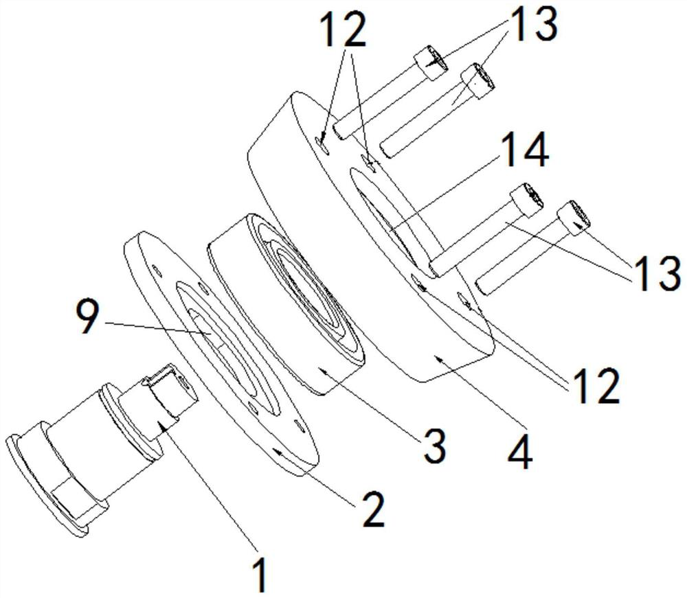
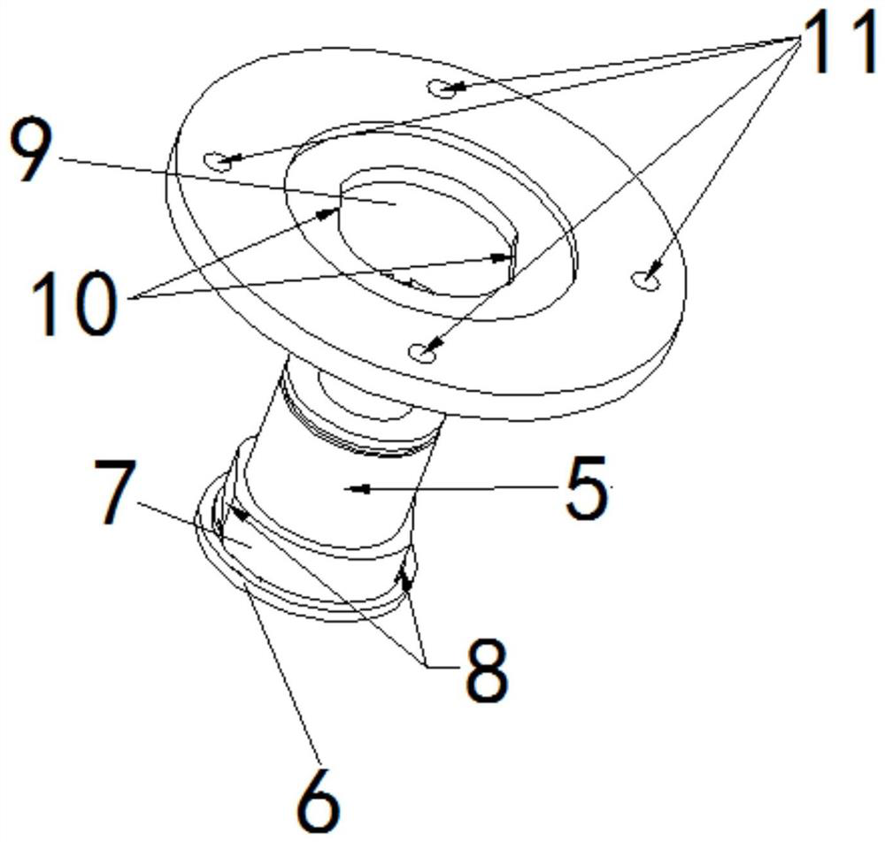
[0022] as attached figure 1 , attached figure 2 As shown, the present invention is a new energy vehicle drive integrated system motor structure, including a motor shaft 1, a bearing plate 2, a bearing 3, a motor rear end cover 4, a bearing chamber is arranged on one side of the motor rear end cover 4, and the motor shaft 1 includes The bearing assembly part 5 and the bearing end surface 6, the pressure plate installation part 7 is set between the bearing assembly part 5 and the bearing end surface 6, the bearing step surface 8 is set at the position of the pressure plate installation part 7, and the middle through ho...


PUM


Abstract

The invention provides a new energy automobile driving integrated system motor structure applied to the technical field of new energy automobiles. The new energy automobile driving integrated system motor structure comprises a motor rotating shaft (1), a bearing pressing plate (2), a bearing (3) and a motor rear end cover (4). A bearing chamber is arranged on one side of the motor rear end cover (4). The motor rotating shaft (1) comprises a bearing assembling part (5) and a bearing end face (6), a pressing plate installing part (7) is arranged between the bearing assembling part (5) and the bearing end face (6), a bearing step face (8) is arranged at the pressing plate installing part (7), a middle through hole (9) is formed in the bearing pressing plate (2), and a pressing plate step face(10) is arranged at the middle through hole. The new energy automobile driving integrated system motor structure is simple in structure, the bearing pressing plate is convenient to install in the newenergy automobile drive integrated system motor, the installation process is simplified, and the installation efficiency is improved.

Description

technical field [0001] The invention belongs to the technical field of new energy vehicles, and more specifically relates to a new energy vehicle drive integration system motor structure. Background technique [0002] With the development of new energy vehicles, the independent main drive motor, reducer and motor controller can no longer meet the requirements of the vehicle manufacturer. Now the vehicle manufacturer needs to use the motor, motor controller and reducer The scheme of machine combined into drive system integration system. [0003] At present, in a traditional driving motor, the bearing outer ring at the front end of the rotor needs to be axially fixed in the bearing chamber of the motor front end cover, and the bearing outer ring is usually fixed axially by a bearing pressure plate. There are multiple threaded holes on the bearing pressure plate, and multiple threaded through holes corresponding to the position of the bearing pressure plate on the motor end co...

Claims


Application Information

Patent Timeline
Patent Type & Authority Applications(China)
IPC IPC(8): H02K5/16H02K5/04H02K7/00H02K7/10H02K7/08
CPCH02K5/04H02K5/16H02K7/003H02K7/08H02K7/10
Inventor 徐凯裴善忠吴瑞邱林
Owner 安徽鸿创新能源动力有限公司
Why Eureka
Try Eureka