Controlling the split of liquid reflux in a dividing wall column

A technology of dividing wall tower and liquid reflux, which is applied in the direction of distillation adjustment/control, separation/purification of carbonyl compounds, fractionation, etc., and can solve problems such as increasing costs

Active Publication Date: 2020-11-24
UOP LLC
View PDF6 Cites 1 Cited by
  • Summary
  • Abstract
  • Description
  • Claims
  • Application Information

AI Technical Summary

Problems solved by technology

Excess acetone in the net side draw aqueous stream and net side draw organic stream would require additional treatment to remove the excess acetone and / or loss of acetone and / or increase the cost of disposal or further processing of the stream containing the excess acetone

Method used


Image

  • Controlling the split of liquid reflux in a dividing wall column
  • Controlling the split of liquid reflux in a dividing wall column

Examples


no. 1 approach

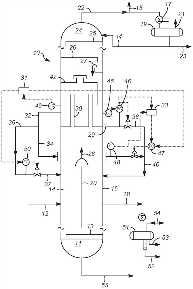
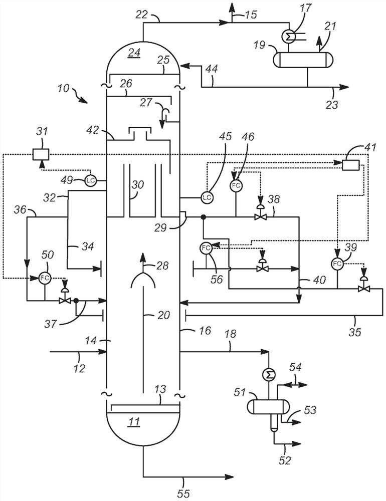
[0033] The first embodiment is a process comprising a dividing wall column 10 having a feed side 14 and a product side 16, wherein the feed side includes an inlet for the feed stream 12, and wherein the product side includes an inlet for the liquid Product line outlet for side draw stream 18; wherein liquid reflux stream 27 from first active distillation tray 26 above dividing wall 20 forms or can form two liquid phases wherein the two liquid phases of the reflux stream pass through any means separation, wherein the reflux stream 29 mainly comprising the aqueous phase is conducted as a whole to the product side of the dividing wall, and the reflux stream 32 mainly comprising the organic phase is divided into streams 34 and 36, wherein stream 34 is conducted as reflux to the product side, and stream 36 is directed as reflux to the feed side, wherein for the split phase stream, the flow split to the product side relative to the feed side is controlled.

[0034] A second embodime...


PUM


Abstract

The present invention relates to the fractionation technology that is used to create purified phenol and acetone products. More specifically, the present invention relates to a fractionation technology that is used to create crude acetone and crude phenol streams using a dividing wall column intended to remove cumene, alpha-methyl styrene and water from the product side of the wall.

Description

[0001] priority statement [0002] This application claims priority to U.S. Application No. 16 / 368,310, filed March 28, 2019, which in turn claims priority to U.S. Provisional Application No. 62 / 650,170, filed March 29, 2018, the entirety of which is incorporated into this article. technical field [0003] The present invention relates to fractional distillation techniques for producing purified phenol products. More specifically, the present invention relates to fractional distillation techniques for the production of crude acetone and crude phenol streams using a dividing wall column designed to remove cumene, alpha-methylstyrene and water. Background technique [0004] Phenol is produced via air oxidation of cumene to cumene hydroperoxide (CHP), followed by acid-catalyzed cleavage of the latter to phenol and acetone, and is referred to as CHP decomposition. CHP decomposition is a very exothermic reaction that is usually performed on a commercial scale in continuously s...

Claims


Application Information

Patent Timeline
Patent Type & Authority Applications(China)
IPC IPC(8): B01D3/14C07C45/82C07C39/04
CPCC07C37/74B01D3/141B01D3/42B01D3/4233C07C39/04C07C37/52B01D2257/7027
Inventor 拉塞尔·C·舒尔茨查德·A·威廉姆斯詹姆斯·W·哈里斯尼康吉·马努拜·帕特尔
Owner UOP LLC
Why Eureka
Try Eureka