Synchronous electrical machine

A technology of synchronous motors and mechanical energy, applied in synchronous generators, synchronous machines, synchronous motors for single-phase current, etc., can solve problems such as generator complexity, reduce maintenance costs, reduce temperature gradients, and improve reliability Effect

Pending Publication Date: 2020-11-24
SAFRAN ELECTRICAL & POWER
View PDF4 Cites 0 Cited by
  • Summary
  • Abstract
  • Description
  • Claims
  • Application Information

AI Technical Summary

Problems solved by technology

These machines are usually generators known as tertiary generators, which are very complex due to transformers and rotating rectifiers

Method used


Image

  • Synchronous electrical machine
  • Synchronous electrical machine
  • Synchronous electrical machine

Examples


Embodiment Construction

[0091] The following examples are examples. Although the description herein refers to one or more embodiments, this does not necessarily mean that every reference refers to the same embodiment or that a feature applies to only one embodiment. Simple features of different embodiments can also be combined to provide other embodiments. In the drawings, for the sake of illustration and clarity, scale and proportion are not strictly adhered to.

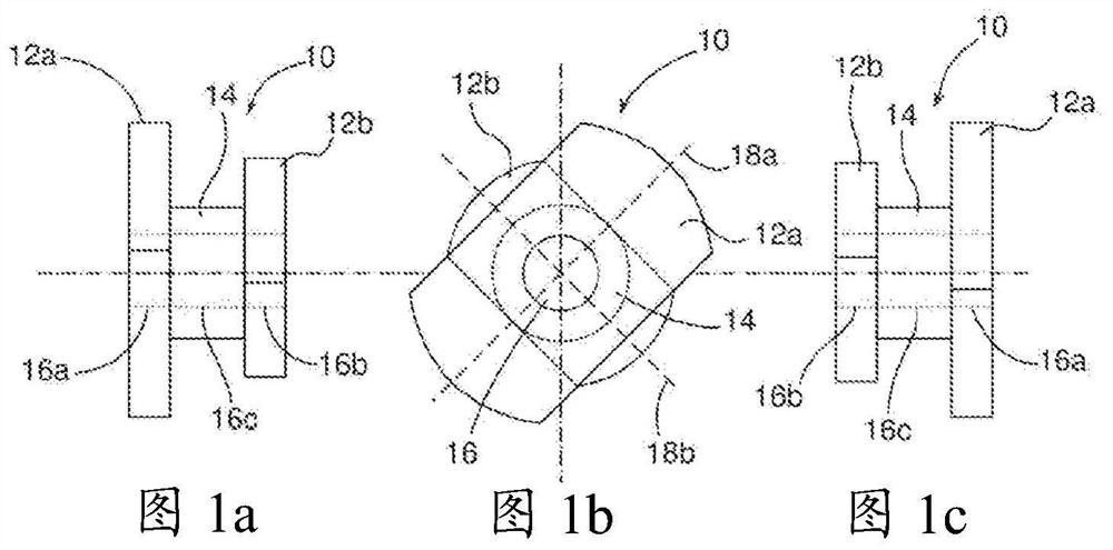
[0092] The following figures describe the components of a brushless and magnetless synchronous machine configured to drive a rotating element about the axis of rotation of the electric machine or from mechanical energy transmitted by the rotating element, according to embodiments of the present invention. generate electricity.

[0093] Figure 1a , Figure 1b and Figure 1c A rotor 10 of an electric machine according to an embodiment of the invention is shown schematically as seen from the right, from the front and from the left, resp...


PUM


Abstract

The invention relates to a brushless and magnet-free synchronous electrical machine, characterized in that it comprises a stator (20) comprising a ring (22), a winding (28) and a tooth system (24) comprising teeth (26) extending parallel to the axis of rotation from the ring (22), said winding being wound around the tooth system (24), a rotor (10), comprising a first portion (12a) extending in p preferred directions (18a), a second portion (12b) extending in p preferred directions (18b) shifted by p with respect to the preferred directions of the first portion (18a), and an intermediate portion (14) linking the first portion (12a) to the second portion (12b), and a coil (40) for exciting the rotor, fixed with respect to the stator, supplied with a DC electric current, positioned around theintermediate portion (14) of the rotor and configured so as to generate an electric flux in the rotor (10) through magnetic induction.

Description

technical field [0001] The present invention relates to the field of electric machines, in particular synchronous machines, which can be used both as electric motors and as generators. In particular, the present invention relates to a brushless and magnetless synchronous machine. Background technique [0002] The prior art specifically includes documents WO-A2-2012 / 085438, US-A-3473061, WO-A1-2016 / 138159, DE-A1-19547016 and FR-A1-2406333. [0003] Synchronous motors with rotor excitation flux are currently divided into two categories: permanent magnet motors and brush motors. [0004] The advantages of permanent magnet motors are that they can achieve high torque density and low rotor losses, but the disadvantages of permanent magnet motors are that they must contain magnets that are expensive to purchase and complicated to manufacture. [0005] In addition, technological developments and their impact on the consumer market are leading to an exponential consumption of cert...

Claims


Application Information

Patent Timeline
Patent Type & Authority Applications(China)
IPC IPC(8): H02K19/20H02K19/10
CPCH02K19/103H02K19/20H02K1/246H02K15/022H02K15/026
Inventor 莱昂内尔·布儒瓦
Owner SAFRAN ELECTRICAL & POWER
Why Eureka
Try Eureka