Air purification system of textile workshop for textile production

An air purification system and workshop technology, applied in the field of textile production, can solve the problems of pungent smell, unguaranteed physical health, affecting the breathing health of workers, etc., and achieve the effect of full combination and better effect.

Inactive Publication Date: 2020-11-27
郝柯柯
View PDF8 Cites 3 Cited by
  • Summary
  • Abstract
  • Description
  • Claims
  • Application Information

AI Technical Summary

Problems solved by technology

[0003] During the operation of the textile production workshop, various cotton flocs are often produced. These cotton flocs float in the air and easily affect the respiratory health of the workers. At the same time, a large amount of dyes are used in the textile production process. The smell of these dyes Pungent, textile workers work in such an environment for a long time, and their health cannot be guaranteed, so how to efficiently remove the pungent smell of these cotton wool and dyes is what we need to consider

Method used


Image

  • Air purification system of textile workshop for textile production
  • Air purification system of textile workshop for textile production
  • Air purification system of textile workshop for textile production

Examples


Embodiment 1

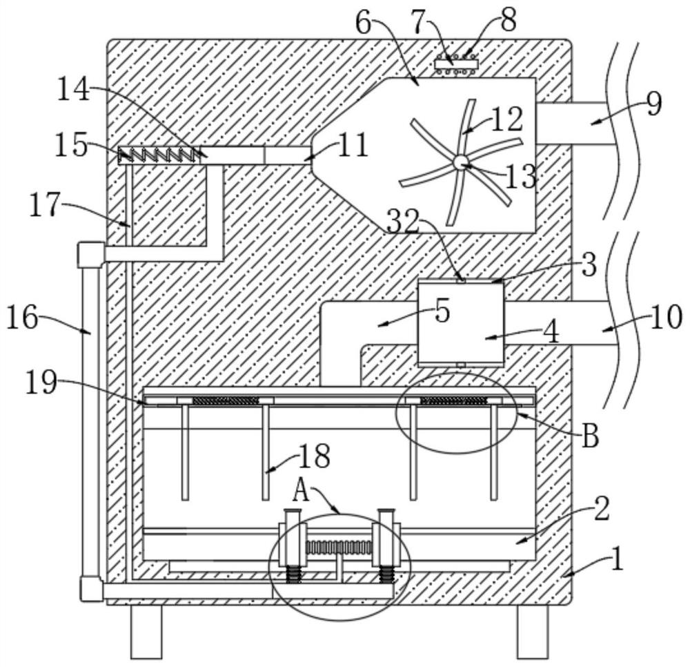
[0025] refer to Figure 1-4 , an air purification system for a textile workshop for textile production, comprising a housing 1, a plurality of support blocks are fixedly connected to the lower end of the housing 1, and a trigger chamber 6, a filter chamber 3 and a filter chamber 3 are arranged in the housing 1 from top to bottom In the processing chamber 2, the left side of the trigger chamber 6 is provided with a transverse groove 11 communicating with it, the right side of the trigger chamber 6 communicates with the outside world through the air inlet pipe 9, and the right side of the filter chamber 3 communicates with the outside world through the air outlet pipe 10;

[0026] The trigger module, the trigger module includes a rotating shaft 13 horizontally arranged in the trigger chamber 6, the two ends of the rotating shaft 13 are respectively connected to the front and rear inner walls of the trigger chamber 6 in rotation, and the rotating shaft 13 is uniformly fixedly conn...

Embodiment 2

[0037] refer to Figure 5-6 , The difference between this embodiment and Embodiment 1 is that the lower end of the rotating rod 32 is rotationally connected with the inner bottom of the filter chamber 3, and the upper end of the rotating rod 32 extends into the trigger chamber 6 and is fixedly connected with the transmission gear 31, the rotating shaft 13 A crown gear 30 is fixedly connected to the top, and the crown gear 30 meshes with the transmission gear 31 .

[0038] In this embodiment, the rotation of the rotating shaft 13 will drive the crown gear 30 to rotate, the rotation of the crown gear 30 will drive the transmission gear 31 to rotate, and the rotation of the transmission gear 31 will drive the rotation rod 32 to rotate, so that the filter cartridge 4 is in a rotating state, thereby The entire filter layer of the filter cartridge 4 is consumed evenly, and the overall service life thereof is increased.


PUM


Abstract

The invention discloses an air purification system of a textile workshop for textile production. The air purification system comprises a shell, a plurality of supporting blocks are fixedly connected to the lower end of the shell, a triggering cavity, a filtering cavity and a treatment chamber are sequentially arranged in the shell from top to bottom, a transverse groove communicating with the triggering cavity is formed in the left side of the triggering cavity, the right side of the triggering cavity communicates with the outside through an air inlet pipe, and the right side of the filteringcavity communicates with the outside through an air outlet pipe; a triggering module comprises a rotating shaft horizontally arranged in the triggering cavity, the two ends of the rotating shaft are rotationally connected with the front inner wall and the rear inner wall of the triggering cavity respectively, and a plurality of impeller blades are evenly and fixedly connected to the rotating shaftin the circumferential direction of the rotating shaft. The system can efficiently remove tiny cotton fibers in the air, meanwhile, toxic and harmful gas generated by dye can be filtered, only one external draught fan needs to be matched in the whole process, and the beneficial effect of being low in energy consumption is achieved.

Description

technical field [0001] The invention relates to the field of textile production, in particular to an air purification system for a textile workshop used in textile production. Background technique [0002] Textile is the assembly of industrial sectors that produce fabrics and fibers, yarns, threads and other raw materials made into fabrics, while textile production workshops refer to workshops that use machinery to manufacture means of production or means of living, and are places where textile raw materials are processed and manufactured; [0003] During the operation of the textile production workshop, various cotton flocs are often produced. These cotton flocs float in the air and easily affect the respiratory health of the workers. At the same time, a large amount of dyes are used in the textile production process. The smell of these dyes Pungent, textile workers work in such an environment for a long time, and their health cannot be guaranteed, so how to efficiently rem...

Claims


Application Information

Patent Timeline
Patent Type & Authority Applications(China)
IPC IPC(8): B01D47/06B01D53/06F24F3/16F24F13/28
CPCB01D47/06B01D53/06B01D2253/102F24F13/28
Inventor 郝柯柯邹海川
Owner 郝柯柯
Why Eureka
Try Eureka