Narrow slit coating unit, method and device
A technology of slit coating and coating method, which is applied in the field of piezoelectric composite material preparation, can solve problems such as low efficiency of electric domain steering, poor polarization effect, and inability to effectively mass produce, so as to improve the polarization effect and save Process time, effect of improving piezoelectric performance
- Summary
- Abstract
- Description
- Claims
- Application Information
AI Technical Summary
Problems solved by technology
Method used
Image
Examples
Embodiment 1
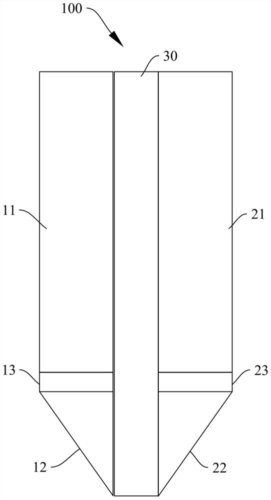
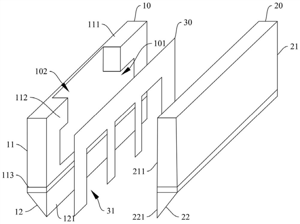
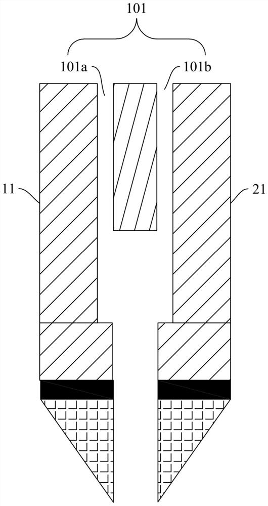
[0059] Please also refer to figure 1 and figure 2 , figure 1 It is a schematic structural view of the slit coating device disclosed in Embodiment 1 of the present invention, figure 2 It is an exploded schematic diagram of the structure of the slit coating device disclosed in the first practical embodiment. The slit coating device disclosed in this embodiment can be applied to slit coating equipment to coat piezoelectric composite materials to form piezoelectric films. Specifically, the slit coating device 100 includes a first clamping block 10 , a second clamping block 20 and an insulating clamping piece 30 . Wherein, the first clamping block 10 includes a first clamping portion 11 and a first electrical connection portion 12 , and the first electrical connection portion 12 is insulated and connected to the first clamping portion 11 . The second clamping block 20 includes a second clamping portion 21 and a second electrical connection portion 22 insulated from the second...
Embodiment 2
[0099] see Figure 6 and the above figure 2 , Figure 5 , is a coating method using a slit coating device disclosed in an embodiment of the present invention. The coating method can use a slit coating device 100 to coat a slurry of a piezoelectric composite material to obtain a piezoelectric film. Specifically, the slit coating device 100 may be the slit coating device 100 described in the first embodiment above, and the coating method may include the following steps:
[0100] 201. Clamp and fix the insulating clip between the first clamping block and the second clamping block.
[0101] The purpose of this step is to fix the insulating clip 30, the first clip 10, and the second clip 20 to form a slit between the first clip 10 and the second clip 20, so as to facilitate the subsequent slurry flow.
[0102] 202. Power on the first power connection part and the second power connection part.
[0103] The purpose of this step is to form an electric field between the first ele...
Embodiment 3
[0116] see Figure 7 , Embodiment 3 of the present invention discloses a slit coating device 300, which may include the slit coating device 100 as described in Embodiment 1 above. Specifically, the slit coating equipment 300 may include a main body 301 of the equipment, and the main body 301 of the equipment may be provided with a pipeline to deliver the slurry to the cavity 101 of the slit coating device 100 through the feed port 102 . At the same time, the equipment main body 301 can be used to control the conveying speed and flow rate of the slurry at the feed port 102, and correspondingly, the electric field intensity formed by the first electrical connection part 12 and the second electrical connection part 22 can also be controlled, and The flow rate of the slurry in the flow channel 31 and the like.
[0117] The slit coating equipment 300 disclosed in Embodiment 3 of the present invention has the functions of coating and polarization of piezoelectric composite slurry b...
PUM
 Abstract
Description
Claims
Application Information
 - R&D
- Intellectual Property
- Life Sciences
- Materials
- Tech Scout
- Unparalleled Data Quality
- Higher Quality Content
- 60% Fewer Hallucinations
Browse by: Latest US Patents, China's latest patents, Technical Efficacy Thesaurus, Application Domain, Technology Topic, Popular Technical Reports.
© 2025 PatSnap. All rights reserved.Legal|Privacy policy|Modern Slavery Act Transparency Statement|Sitemap|About US| Contact US: help@patsnap.com


