
High-power ultraviolet picosecond laser processing system

A processing system and high-power technology, applied in laser welding equipment, metal processing equipment, manufacturing tools, etc., can solve the problems of poor material cooling effect, affecting material processing, inconvenient transportation of overheated materials, etc.

Active Publication Date: 2020-11-27
苏州曼德特光电技术有限公司
View PDF5 Cites 2 Cited by
  • Summary
  • Abstract
  • Description
  • Claims
  • Application Information

AI Technical Summary

Problems solved by technology

[0005] The technical problem to be solved by the present invention is to provide a high-power ultraviolet picosecond laser processing system to solve the problem that the existing high-power ultraviolet picosecond laser processing system is inconvenient to transport overheated materials and easily affects the processing and processing of subsequent materials. The problem of poor cooling effect on materials

Method used


Image

  • High-power ultraviolet picosecond laser processing system
  • High-power ultraviolet picosecond laser processing system
  • High-power ultraviolet picosecond laser processing system

Examples


Embodiment Construction

[0031] The present invention will be further described below in conjunction with accompanying drawing:

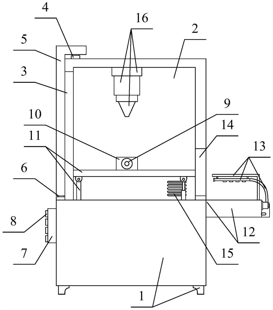
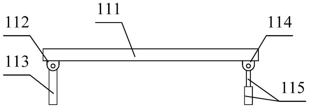
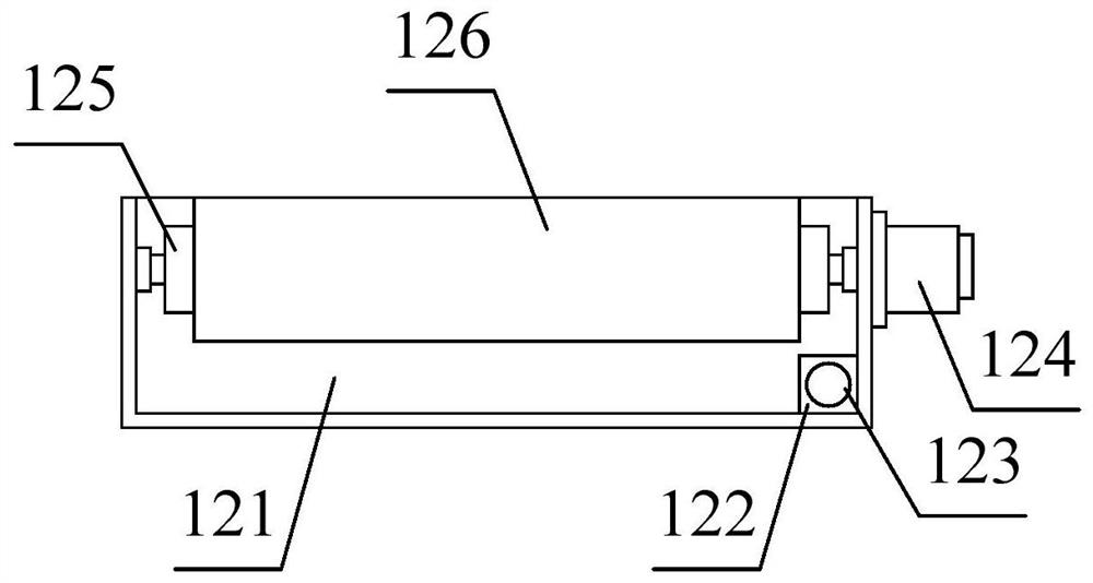
[0032] as attached figure 1 And attached figure 2 As shown, a high-power ultraviolet picosecond laser processing system according to the present invention includes a body 1, a mounting shell 2, a placement hole 3, a slide rail 4, a slide plate 5, a slide block 6, a PLC 7, a drive switch 8, Clamping cylinder 9, clamping plate 10, tiltable transport table structure 11, transportable box structure 12, water spray cooling tube frame structure 13, penetration hole 14, air outlet hole 15 and optical fiber laser puncher 16, said The mounting shell 2 bolts are installed on the upper end of the body 1; the placement hole 3 is opened on the left side of the inner wall of the mounting shell 2; the slide rail 4 is respectively bolted to the left side of the upper surface of the body 1 and the upper surface of the mounting shell 2 the left side; the slider 6 is respectively bolt-moun...


PUM


Abstract

The invention discloses a high-power ultraviolet picosecond laser processing system comprising a machine body, a mounting shell, a placing hole, a sliding rail, a sliding plate, a sliding block, a PLC, a driving switch, a clamping air cylinder, a clamping plate, a tiltable conveying table structure, a conveying box structure, a cooling pipe frame structure capable of spraying water, a penetratinghole, an air outlet and an optical fiber laser puncher, and the mounting shell is mounted at the upper end of the machine body through bolts; the placing hole is formed in the left side of the inner wall of the mounting shell; and the sliding rail is correspondingly installed on the left side of the upper surface of the machine body and the left side of the upper surface of the mounting shell through bolts. The high-power ultraviolet picosecond laser processing system has the beneficial effects that the tiltable conveying table structure is arranged, a placing table can be driven to tilt rightwards after a lifting air cylinder is driven, and therefore parts on the placing table are better enabled to slide and move to a designated position, and then other parts are conveniently placed for processing.

Description

technical field [0001] The invention belongs to the technical field of high-power ultraviolet picosecond laser processing, and in particular relates to a high-power ultraviolet picosecond laser processing system. Background technique [0002] After the picosecond laser drilling machine performs the drilling process of the parts, it will generate a higher temperature on the parts, so a picosecond laser drilling machine with cooling function is improved, so as to better process the parts, and at the same time It is also convenient to place or take parts, and to improve work efficiency. [0003] However, the existing high-power ultraviolet picosecond laser processing system still has the problems of being inconvenient to transport overheated materials, easily affecting the processing of subsequent materials, and having a poor cooling effect on materials. [0004] Therefore, it is very necessary to invent a high-power ultraviolet picosecond laser processing system. Contents o...

Claims


Application Information

Patent Timeline
IPC IPC(8): B23K26/382B23K26/14B23K26/70
CPCB23K26/382B23K26/14B23K26/702
Inventor 张琦
Owner 苏州曼德特光电技术有限公司
Learn More