Hydraulic system hose withhold machine

A technology of hydraulic system and crimping machine, which is applied in the field of hydraulic system hose crimping machine, can solve the problems that it is difficult to ensure the radial force of the extrusion block, reduce the accuracy and efficiency of crimping, extrusion deformation and extrusion sealing, etc., and achieve improvement Withholding accuracy and efficiency, good shock absorption effect, and the effect of increasing the contact area

Active Publication Date: 2020-11-27
南京鑫姆迪克液压技术有限公司
View PDF14 Cites 4 Cited by
  • Summary
  • Abstract
  • Description
  • Claims
  • Application Information

AI Technical Summary

Problems solved by technology

[0004] In view of the above-mentioned related technologies, the inventor believes that there are the following defects: in actual processing, the personnel put the joint on the hydraulic system pipe and extend it into the crimping machine, and use the crimping block to fix the hydraulic system pipe and the joint to crimp, but During the process of putting the joint and the hydraulic system tube into the crimping machine, the joint and the rubber hose are in a loose state, and the joint is easy to fall off from the hose. It is difficult to ensure that the radial force of each extrusion block is consistent during the crimping process, which may easily cause the During the crimping process, the tube is extruded and deformed or the extrusion sealing is not good, which reduces the crimping accuracy and efficiency

Method used


Image

  • Hydraulic system hose withhold machine
  • Hydraulic system hose withhold machine
  • Hydraulic system hose withhold machine

Examples


Embodiment Construction

[0046] The following is attached Figure 1-9 The application is described in further detail.

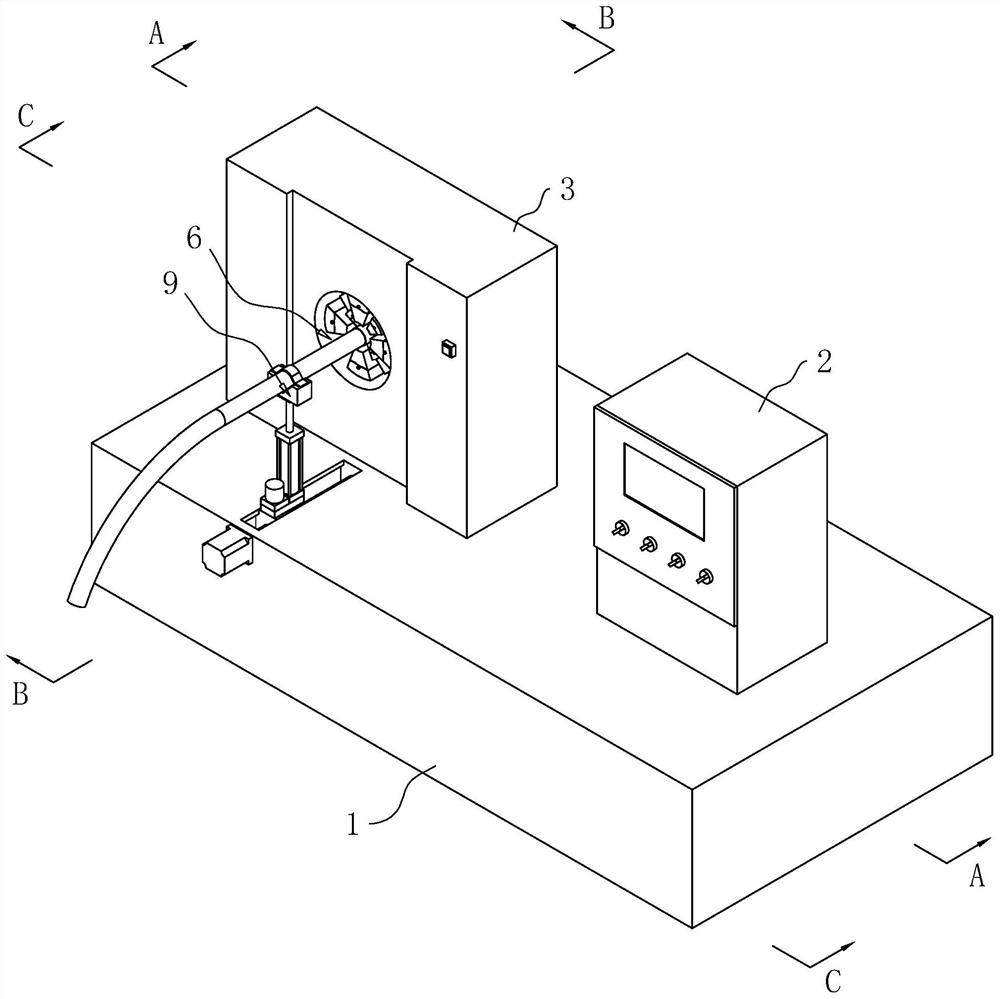
[0047] The embodiment of the present application discloses a hydraulic system hose crimping machine. refer to figure 1 The crimping machine includes a workbench 1, a control box 2 installed on the workbench 1, and a clamping seat 3 located on one side of the control box 2. The middle part of the side wall of the clamping seat 3 is provided with a clamping groove 6. In this embodiment, The longitudinal section of the clamping groove 6 is circular, and the clamping groove 6 is a through groove, and the clamping groove 6 runs through the two side walls of the clamping pipe seat 3 respectively, so that the hose provided with the connector can be inserted into the clamping groove 6 .

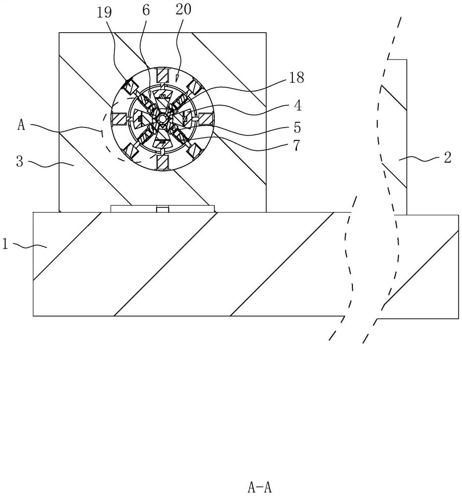
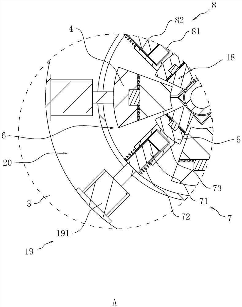
[0048] refer to figure 1 and figure 2 , a number of first arc blocks 4 are arranged in the clamping groove 6 and along its own circumferential array, a second arc block 5 is arranged between two adjace...


PUM


Abstract

The invention provides a hydraulic system hose withhold machine and relates to the field of withhold machines. The hydraulic system hose withhold machine comprises a working table, and further comprises a pipe clamping base mounted on the working table, a plurality of first arc blocks arrayed in the circumferential direction of a hose and second arc blocks located between the adjacent first arc blocks. The sidewall of the pipe clamping base is provided with clamping grooves for accommodating the first arc blocks and the second arc blocks. Elastic guide assemblies used for driving the second arc blocks to move in the radial direction of the clamping grooves are arranged on the groove walls of the clamping grooves. A locating and retaining assembly used for bearing the hose is arranged on the working table. The outer arc walls of the first arc blocks and the second arc blocks are all provided with abutting assemblies abutting against the outer wall of a joint. The pipe clamping base is internally provided with a cavity communicating with the clamping grooves. A driving assembly used for driving the first arc blocks and the second arc blocks to slide in the radial direction of the sliding grooves is arranged in the cavity. The hydraulic system hose withhold machine has the advantages of preventing extrusion deformation and poor airtightness caused by looseness between the joint and the rubber hose and improving the withhold precision and efficiency.

Description

technical field [0001] The present application relates to the field of crimping machines, in particular to a hydraulic system hose crimping machine. Background technique [0002] The crimping machine is a kind of hydraulic equipment used for crimping the pipe fitting assembly. It applies shrinkage force to the matching metal joint through the mold of the crimping machine, and firmly crimps the metal joint on the high-pressure oil pipe for the supporting construction machinery or the car. Brake pipes, engine oil pipes, air conditioning pipes, and power pipes. [0003] The Chinese patent with the notification number CN107470883A discloses a hydraulic system pipe crimping machine, including a main machine and a crimping machine connected to the main machine through connecting wires. The crimping machine is arranged on a workbench, and a positioning rod and a mirror are arranged on the crimping machine , bearing block, dust-proof layer, connecting rod, buckle ring installation ...

Claims


Application Information

Patent Timeline
Patent Type & Authority Applications(China)
IPC IPC(8): B23P19/02
CPCB23P19/02
Inventor 吴缪宏张斌
Owner 南京鑫姆迪克液压技术有限公司
Why Eureka
Try Eureka