Device for glazing ceramic cups
A technology for ceramic cups and equipment, which is applied to ceramic molding machines, manufacturing tools, etc., can solve the problems of slow glazing speed and difficult to control the height of ceramic cups, and achieve the effect of fast glazing and rapid glazing.
- Summary
- Abstract
- Description
- Claims
- Application Information
AI Technical Summary
Problems solved by technology
Method used
Image
Examples
Embodiment 1
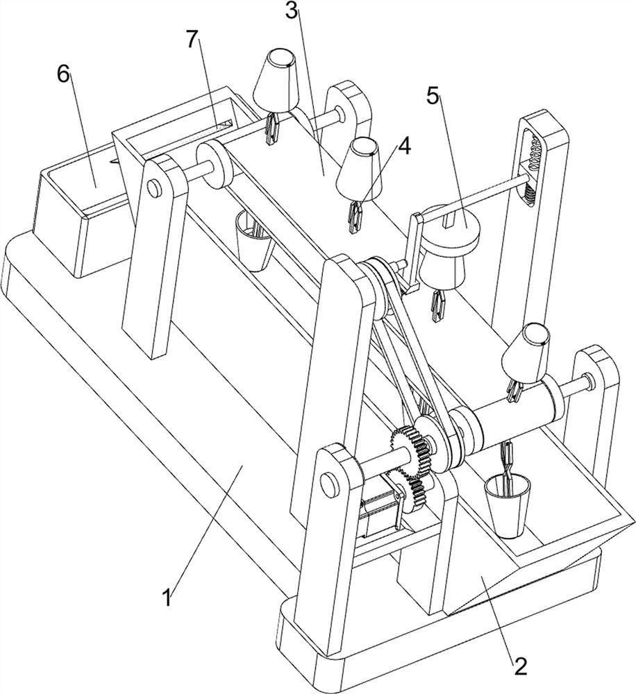
[0022] A device for glazing ceramic mugs such as figure 1 As shown, it includes a bottom plate 1, a charging trough 2, a transmission mechanism 3, a clamping mechanism 4 and a pressing mechanism 5. A charging trough 2 is provided on the rear side of the upper part of the bottom plate 1, and a transmission mechanism 3 is provided on the upper part of the bottom plate 1. The charging trough 2 is located below the transmission mechanism 3, and a plurality of clamping mechanisms 4 are evenly spaced on the transmission mechanism 3, and a pressing mechanism 5 is provided in the middle of the upper part of the bottom plate 1.
[0023] When the user needs to glaze the ceramic cup, this equipment can be used. First, the user can pour the glaze slurry into the charging tank 2, and then place the ceramic cup to be glazed on the clamping mechanism 4, and then move the ceramic cup to be glazed to the charging tank 2 through the transmission mechanism 3, so that the ceramic cup can be glaze...
Embodiment 2
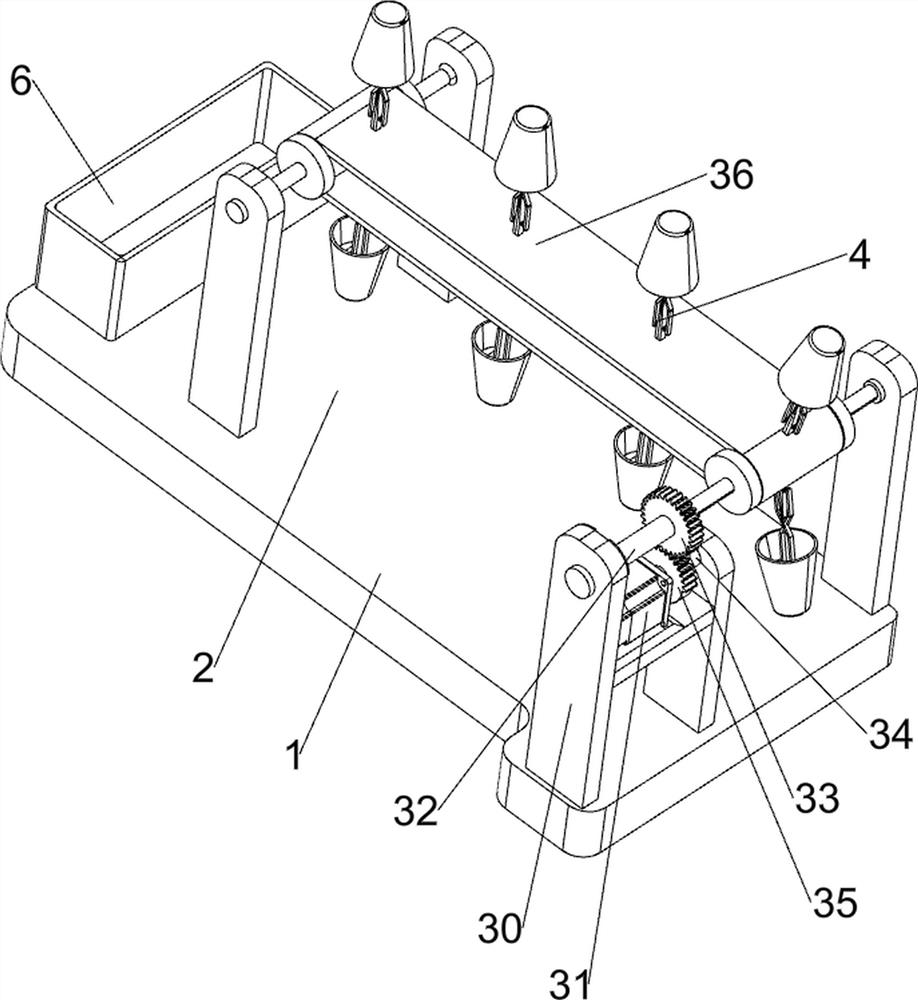
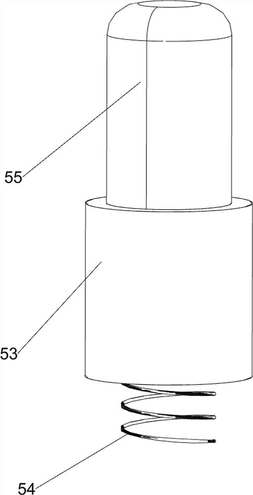
[0025] On the basis of Example 1, such as Figure 1-5 As shown, the transmission mechanism 3 includes a first bearing seat 30, a servo motor 31, a first rotating shaft 32, a full gear 33, a second rotating shaft 34, a missing gear 35, a conveyor belt 36 and a second bearing seat 37. The front and back symmetry of the side is provided with a bearing seat, and the first rotating shaft 32 is arranged in a rotating manner between the two bearing seats on the left and right sides. A conveyor belt 36 is connected between the rotating shafts 32. A second bearing seat 37 is provided on the right front side of the upper part of the base plate 1. The second bearing seat 37 is located at the rear side of the first bearing seat 30 on the right front side. The second bearing seat 37 is provided with a servo drive. Motor 31, the second shaft 37 is rotatably provided with a second rotating shaft 34, the second rotating shaft 34 is connected with the output shaft of the servo motor 31, the se...
Embodiment 3
[0032] On the basis of Example 2, such as figure 1 As shown, a material storage tank 6 is also included, and a material storage tank 6 is installed on the left side of the upper part of the base plate 1, and a control dye capacity tank 7 is opened on the left side of the charging tank 2.
[0033] The user can pour glaze slurry into the charging tank 2. In order to prevent the glaze slurry from flowing into the ceramic cup during the glazing process of the ceramic cup, when there is too much glaze slurry in the charging tank 2, the glaze slurry will pass through to control the dye capacity. The tank 7 flows into the storage tank 6. When the glaze slurry in the storage tank 6 reaches a certain amount, the glaze slurry in the storage tank 6 can be poured back into the charging tank 2, so that the glaze slurry can be reused.
PUM
 Abstract
Description
Claims
Application Information
 - R&D
- Intellectual Property
- Life Sciences
- Materials
- Tech Scout
- Unparalleled Data Quality
- Higher Quality Content
- 60% Fewer Hallucinations
Browse by: Latest US Patents, China's latest patents, Technical Efficacy Thesaurus, Application Domain, Technology Topic, Popular Technical Reports.
© 2025 PatSnap. All rights reserved.Legal|Privacy policy|Modern Slavery Act Transparency Statement|Sitemap|About US| Contact US: help@patsnap.com


