Eureka AIR delivers breakthrough ideas for toughest innovation challenges, trusted by R&D personnel around the world.

Rotary spherical trash rack

A trash rack and rotary technology, applied in the field of rotating spherical trash racks, can solve the problems of clogging the water outlet and hindering the water flow rate of the water inlet, and achieve the effects of increasing water intake, simple structure and convenient use.

Pending Publication Date: 2020-11-27
江西省赣抚平原水利工程管理局
View PDF0 Cites 0 Cited by
  • Summary
  • Abstract
  • Description
  • Claims
  • Application Information

AI Technical Summary

Problems solved by technology

The traditional trash rack not only hinders the flow rate of water at the water inlet, but also easily traps dirt such as aquatic plants and branches at the trash rack opening, blocking the water diversion port

Method used


Image

  • Rotary spherical trash rack
  • Rotary spherical trash rack
  • Rotary spherical trash rack

Examples


Embodiment Construction

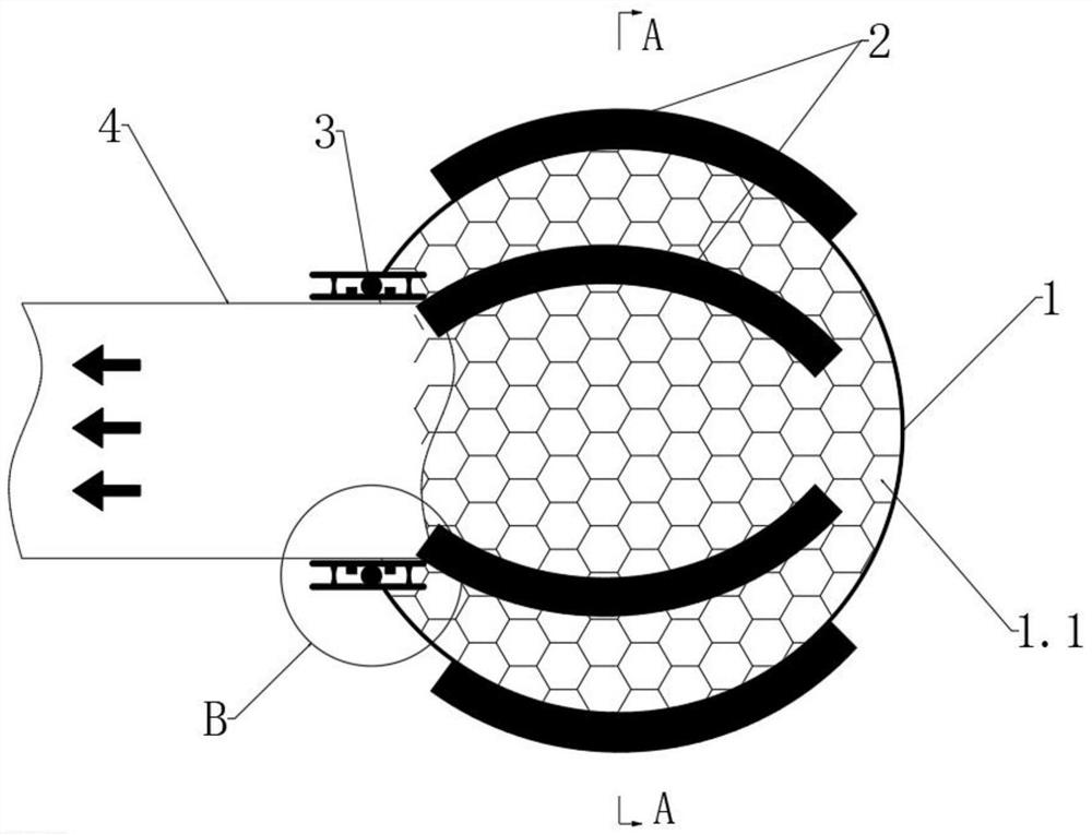
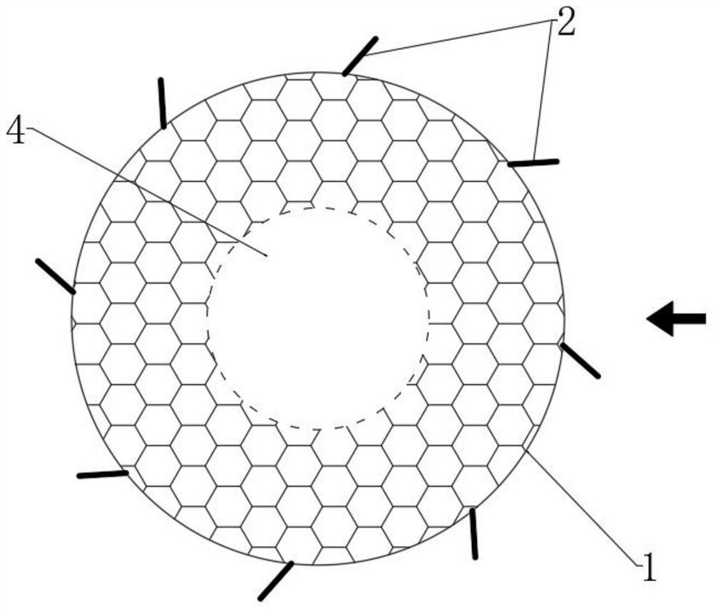
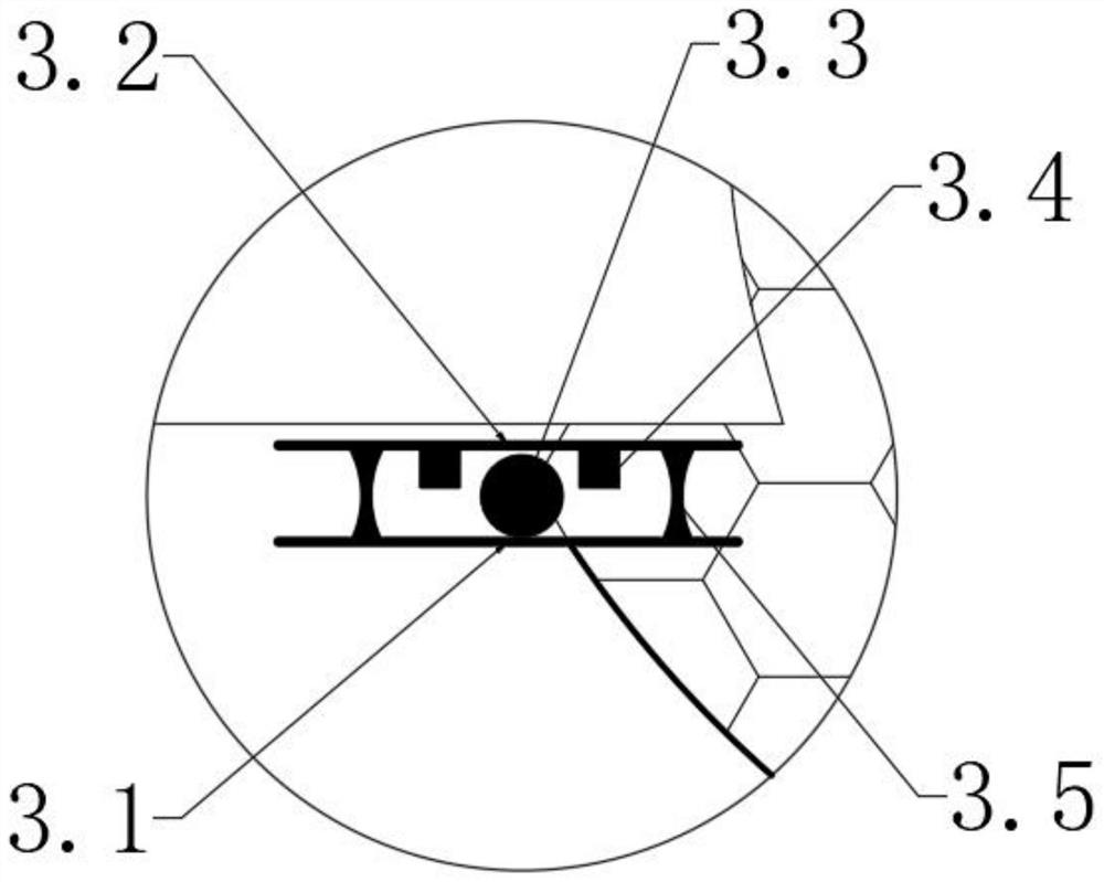
[0016] combined with Figure 1~2 , a rotating spherical trash rack, comprising a trash rack 1, the trash rack 1 is in a spherical shape, and its outer ring is provided with a rotating blade 2 fixedly connected to it, and the trash rack 1 is connected to the trash rack by a rotating device 3 The water pipe 4 is connected in a rotating and sealed manner, and the central axis of the rotating device 3 is on the same axis as the central axis of rotation of the trash rack 1 and the rotating blade 2 .

[0017] As a preferred implementation of this embodiment, the trash rack 1 is provided with uniformly arranged grid holes 1.1 along its spherical surface, and the grid holes 1.1 are in the shape of a regular hexagon.

[0018] As a preferred implementation of this embodiment, the rotating blades 2 are in the shape of fan blade arcs, which are evenly arranged on the outer ring of the trash rack 1 .

[0019] As a preferred implementation of this embodiment, the rotating device 3 includes...


PUM


Abstract

The invention discloses a rotary spherical trash rack. The rotary spherical trash rack comprises a trash rack body, wherein the trash rack body is spherical, and rotary blades fixedly connected with the trash rack body are arranged on an outer ring of the trash rack body; the trash rack body is in rotary sealing connection with a water pipe through a rotation device; and the central axis of the rotation device and the rotary central axes of the trash rack body and the rotary blades are located on the same axis. The rotary spherical trash rack is simple in structure and convenient to use, prevents aquatic plants, branches and the like from staying at a trash rack port to block a water diversion port, and meanwhile effectively increases the water inlet amount of a water inlet port of the water pipe.

Description

technical field [0001] The invention relates to the technical field of trash arresting devices, in particular to a rotary spherical trash rack. Background technique [0002] The trash rack is a grid structure installed in front of the water inlet to block water plants, driftwood and other sundries carried by the water flow. The traditional trash rack is composed of a frame, a diaphragm and a grid, and is generally constructed of steel. The grid spacing depends on the size, amount and application requirements of the dirt. After the trash rack intercepts the dirt, it will hinder the water flow, and with the increase of the amount of dirt, the water level difference between the front and rear of the grid will gradually increase. In order to ensure the safe operation of the ditch and the normal operation of the trash rack, it is necessary to timely clear dirt and reduce head loss. The traditional trash rack not only hinders the flow rate of water at the water inlet, but also ...

Claims


Application Information

Patent Timeline
IPC IPC(8): E02B5/08
CPCE02B5/085
Inventor 谢亨旺靳伟荣张金生龚来红
Owner 江西省赣抚平原水利工程管理局
Why Eureka
Eureka Blog
Learn More