Shaft end hydraulic band-type brake

A hydraulic and shaft-end technology, applied in the direction of shock absorbers, hoisting devices, mechanical equipment, etc., can solve the problems of short replacement cycle, poor heat dissipation performance, fast wear, etc., and achieve the effect of simple structure and strong practicability

Inactive Publication Date: 2020-11-27
马鞍山英维爱生态科技有限公司
View PDF0 Cites 0 Cited by
  • Summary
  • Abstract
  • Description
  • Claims
  • Application Information

AI Technical Summary

Problems solved by technology

The brake pads used in existing hydraulic brakes are mostly made of asbestos fleece friction materials, which wear quickly during use and have poor heat dissipation performance, and the replacement cycle is short

Method used


Image

  • Shaft end hydraulic band-type brake
  • Shaft end hydraulic band-type brake
  • Shaft end hydraulic band-type brake

Examples


Embodiment Construction

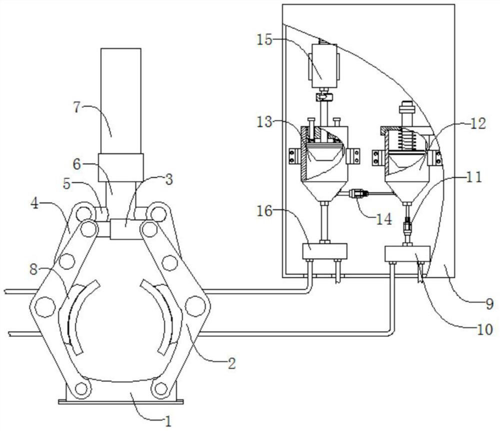
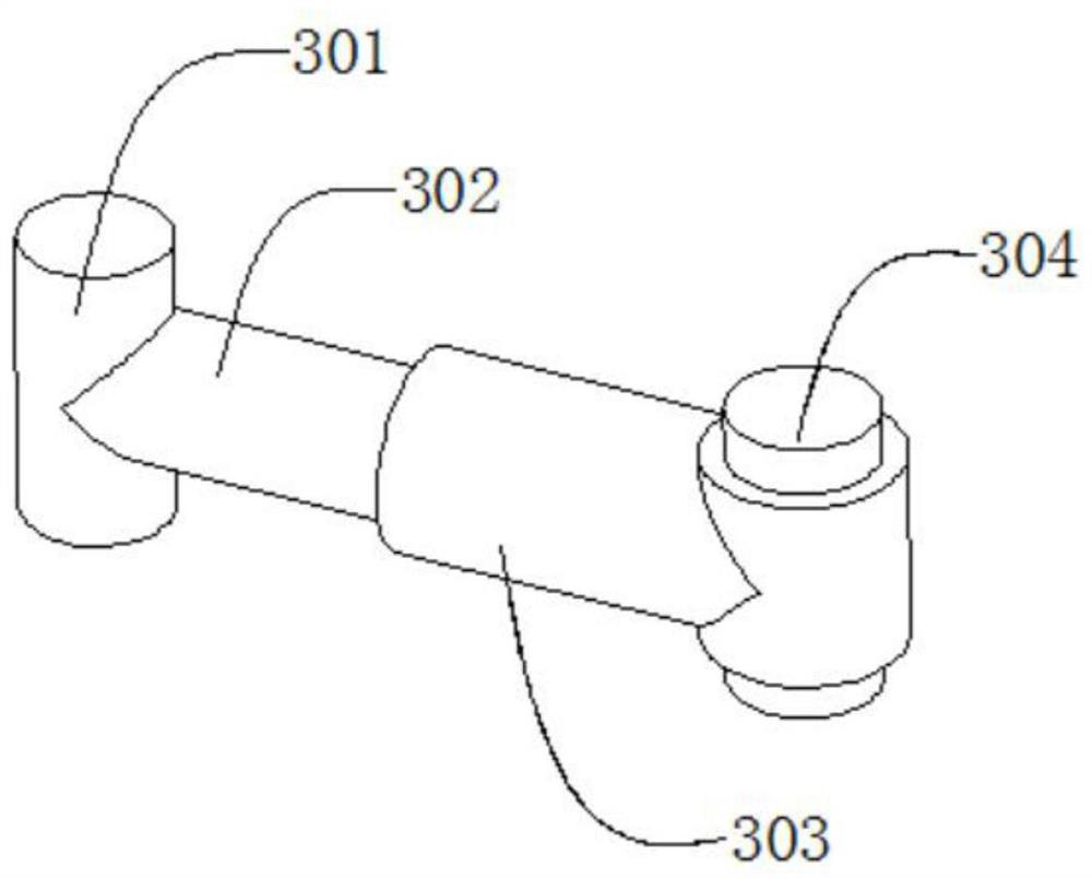
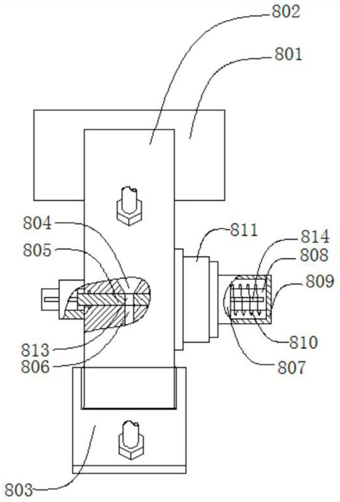
[0020] Such as Figure 1 to Figure 5As shown, an elevator brake device includes a base 1, a support frame 2, a guide mechanism 3, a pressure rod 4, a final shaft 5, a push sleeve 6, an oil cylinder 7, a brake mechanism 8, a housing 9, and a first liquid distribution block 10 , the first one-way valve 11, the buffer mechanism 12, the extrusion mechanism 13, the second one-way valve 14, the long-stroke electromagnet 15, the second liquid-distributing block 16, the number of the support frame 2 is 2 pieces, along the base The left and right directions of 1 are symmetrically arranged, and the guide mechanism 3 is located between two symmetrically arranged support frames 2, and the described guide mechanism 3 is respectively connected to the two symmetrically arranged support frames 2 with clearance fit, and the described support frame 2 is also provided with a pressure rod 4, the pressure rod 4 is connected to the support frame 2 with clearance fit, the pressure shaft 5 is located...


PUM


Abstract

The invention discloses a shaft end hydraulic band-type brake. The shaft end hydraulic band-type brake comprises a base, supporting frames, a guide mechanism, pressing rods, a pressing shaft, a pushing sleeve, an oil cylinder, braking mechanisms, a shell, a first liquid separation block, a first one-way valve, a temporary storage mechanism, an extrusion mechanism, a second one-way valve, a long-stroke electromagnet and a second liquid separation block; and during braking, annular electromagnets arranged in the braking mechanisms are energized and attract attraction sleeves, the long-stroke electromagnet pushes the extrusion mechanism to press non-Newtonian fluid into arc-shaped grooves, transient solid is formed due to the fact that the viscosity of the non-Newtonian fluid in the arc-shaped grooves is extremely high at the moment when brake pads make contact with a high-speed working shaft to brake and buffer vibration of the working shaft, and the non-Newtonian fluid cools the workingshaft until the working shaft is completely stopped along with reduction of the speed of the working shaft. The device is simple in structure, and the functions of braking, vibration buffering and cooling are achieved through the change of the viscosity of the non-Newtonian fluid, so that the service life of the brake pads is prolonged, working vibration is reduced, and high practicability is achieved.

Description

technical field [0001] The invention relates to a mechanical brake, in particular to a shaft end hydraulic brake. Background technique [0002] The hydraulic brake is the so-called hydraulic brake, which is a mechanical part that stops or slows down the moving parts in the machine. In order to reduce the braking torque and structural size, hydraulic brakes are usually installed on the high-speed shaft of the equipment, but large equipment with high safety requirements (such as mine hoists, elevators, etc.) are installed on the low-speed shaft close to the working part of the equipment. On the shaft, some brakes have been standardized and serialized, and are manufactured by professional factories for selection. The brake pads used in the existing hydraulic brakes are mostly made of asbestos fleece friction materials, which wear quickly during use and have poor heat dissipation performance, and the replacement cycle is short. In view of the above defects, it is necessary to ...

Claims


Application Information

Patent Timeline
Patent Type & Authority Applications(China)
IPC IPC(8): F16D49/16F16D65/18F16D65/80F16F15/023B66D5/00F16D121/04
CPCB66D5/00F16D49/16F16D65/18F16D65/80F16D2065/788F16D2121/04F16F15/023F16F2224/04
Inventor 游常青汪彪杨小龙
Owner 马鞍山英维爱生态科技有限公司
Why Eureka
Try Eureka