Engineering machinery working lamp

A technology for construction machinery and work lights, which is applied to the loss prevention measures of lighting devices, lighting and heating equipment, lighting devices, etc. The effect of preventing dust from entering the interior and avoiding excessive dust accumulation

Inactive Publication Date: 2020-11-27
周赢赢
View PDF0 Cites 0 Cited by
  • Summary
  • Abstract
  • Description
  • Claims
  • Application Information

AI Technical Summary

Problems solved by technology

[0002] Work lights are installed on construction machinery for irradiation. They are generally located at the front end of construction equipment to provide a good line of sight for night operations. Dust enters the interior, so there is more dust inside the lampshade, resulting in a decrease in light intensity, and the light moves with the equipment under construction vibration. When the vibration frequency is too high, it is easy to cause polarization. The rapid shaking of the light will cause the vision to form. A sense of confusion, because the continuous irregular movement of the light source point is faster than the human body's reaction speed, which easily causes the human body to form visual fatigue

Method used


Image

  • Engineering machinery working lamp
  • Engineering machinery working lamp
  • Engineering machinery working lamp

Examples


Embodiment 1

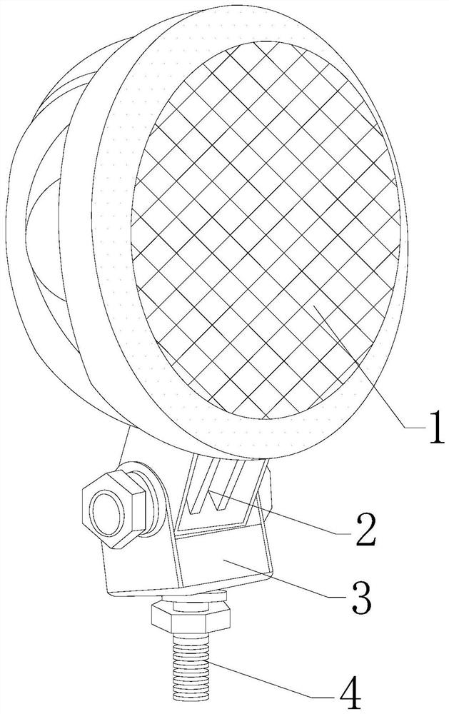
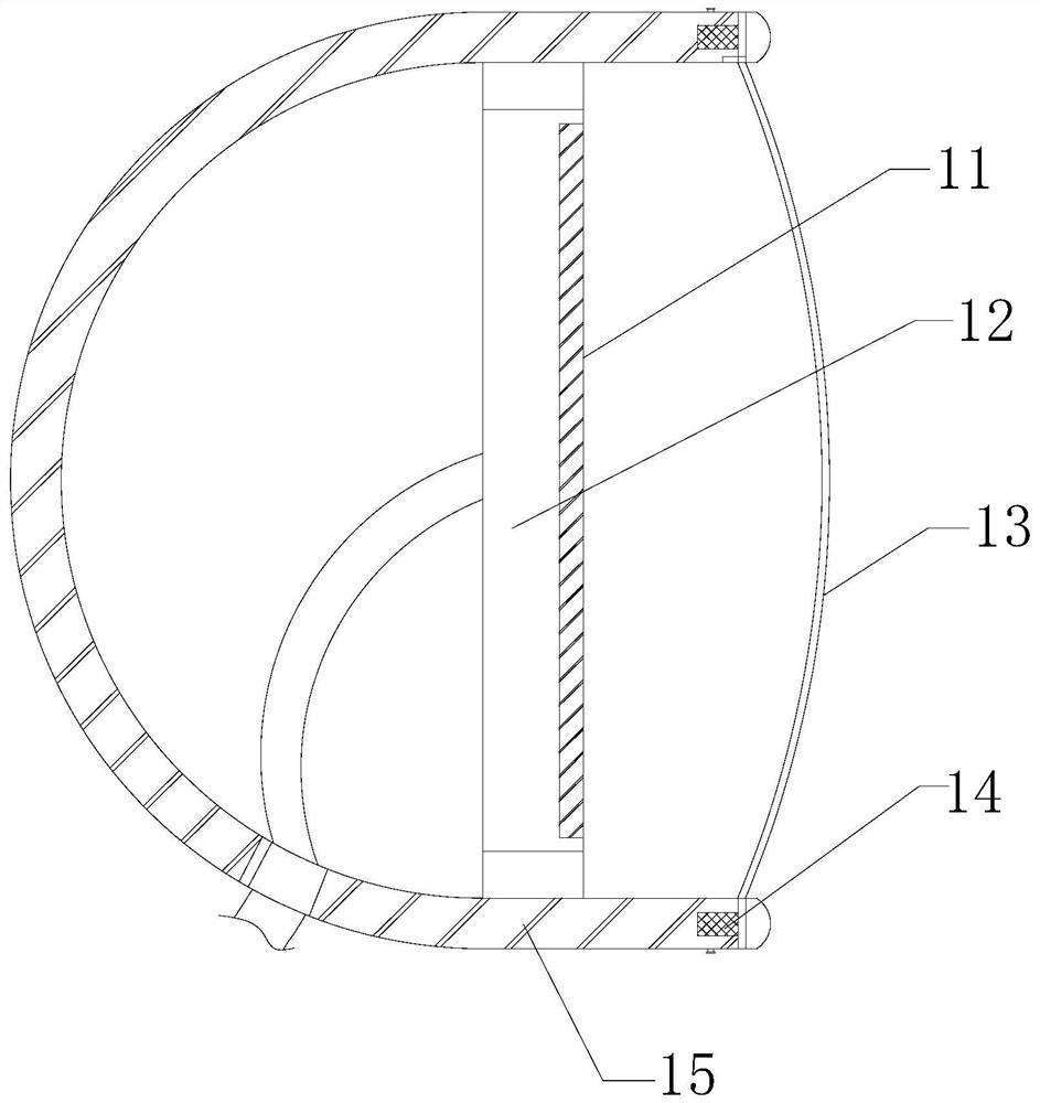
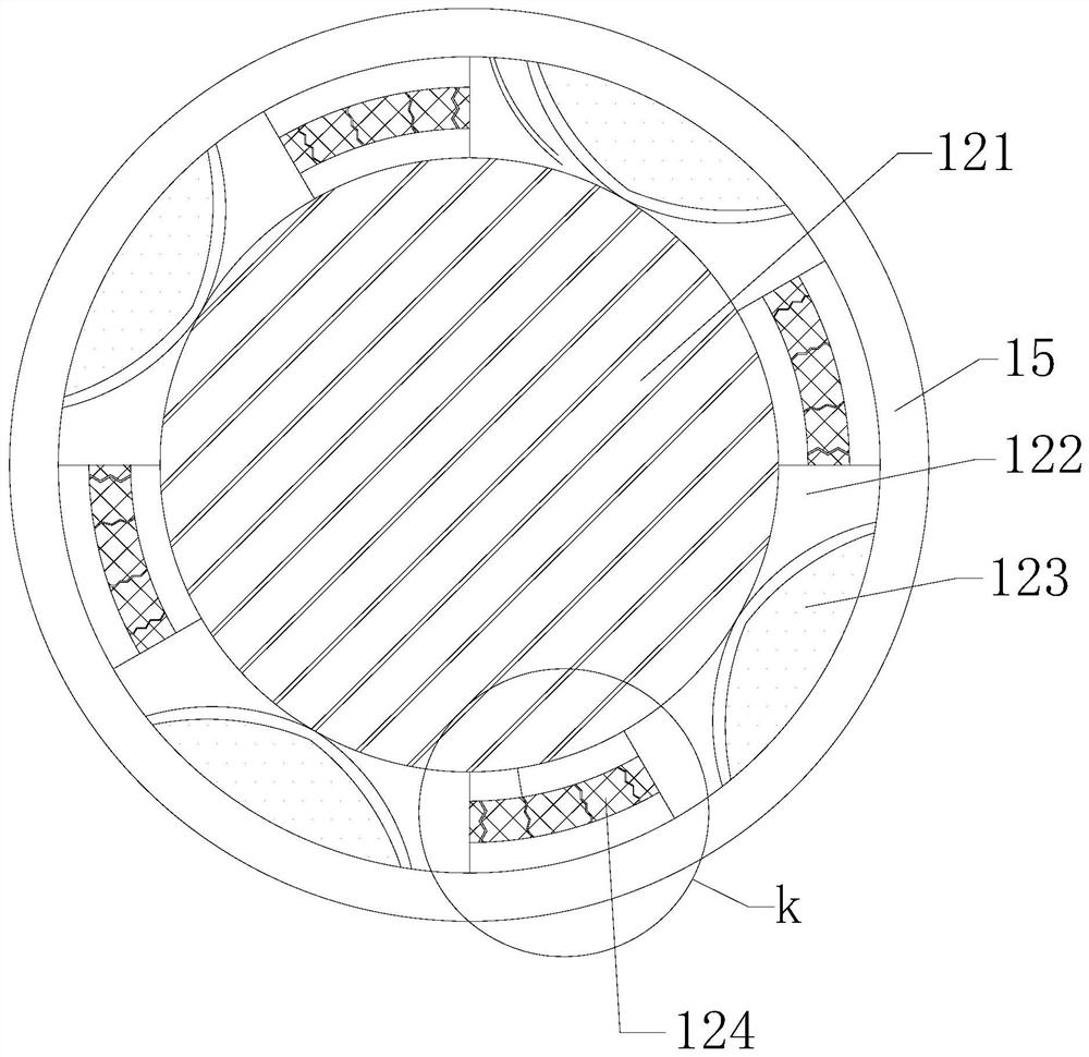
[0023] Such as Figure 1-Figure 5 Shown:

[0024] The present invention is a working light for engineering machinery, the structure of which includes a lamp 1, an engaging block 2, a rotating block 3, and a threaded rod 4. The threaded rod 4 runs through the middle of the lower end of the rotating block 3, and the engaging block 2 is embedded in the In the middle of the rotating block 3, the upper end of the engaging block 2 is welded to the lower end of the lamp 1. The lamp 1 is provided with a lighting board 11, a buffer mechanism 12, a lampshade 13, a sealing mechanism 14, and a lamp holder plate 15. The lighting board 11 Embedded on the right side of the buffer mechanism 12, the outer side of the buffer mechanism 12 is attached to the inner side of the lamp holder plate 15, the sealing mechanism 14 is installed on the right side of the lamp holder plate 15, and the outer side of the lampshade 13 is embedded in the sealing mechanism 14, the lower end of the lamp holder pla...

Embodiment 2

[0031] Such as Figure 6-Figure 7 Shown:

[0032] Wherein, the sealing mechanism 14 is provided with a fixed rod b1, a compression mechanism b2, a plastic plate b3, a connecting block b4, a pressing block b5, and an elastic block b6. The fixed rod b1 is welded on the left side of the connecting block b4. b1 runs through the middle of the plastic plate b3, the compression mechanism b2 is attached to the left side of the upper end of the plastic plate b3, the pressing block b5 is located at the lower end of the elastic block b6, and the elastic block b6 is embedded in the lower end of the left side of the fixed rod b1, so The fixing rod b1 is fixed inside the lamp holder plate 15, there is a round hole in the middle of the plastic board b3, and its upper end is connected with the lampshade 13, and the upper end of the pressing block b5 has a spring structure and is welded with the fixing rod b1, so that the fixed The rod b1 acts on the elastic block b6 through the control of th...


PUM


Abstract

The invention discloses an engineering machinery working lamp. The lamp structurally comprises a lamp body, a clamping block, a rotating block and a threaded rod. The lamp body is provided with a lamplight plate, a buffer mechanism, a lampshade, a sealing mechanism and a lamp holder plate. A rubber plate in a damping mechanism is stressed to extrude the sealing cover, therefore, the bending platesare stressed to bend inwards and acts on the lamp holder plate, shaking of the irradiation plate cannot follow vibration of the lamp holder plate, the polarization phenomenon caused by too fast vibration of the lamp holder plate is prevented, and the disordered feeling caused by fast shaking of the lamp light plate is avoided. The irradiation plate rotates, the shaking speed of the lamplight plate is prevented from being too high, impact on human vision is reduced, the rubber strip is attached to the plastic plate, so that rightward acting force is generated by the hollow groove to be tightlyattached to the plastic plate, and meanwhile the plastic plate and the rubber strip are rubbed through vibration force, tight attachment of the blocking plate and the rubber strip is caused, gaps areprevented from being generated when the plastic plate is embedded and fixed through vibration, dust is prevented from entering the interior, much dust is prevented from being accumulated in the leftside of the lampshade, and the situation that the illumination intensity is reduced is avoided.

Description

technical field [0001] The invention relates to the field of engineering machinery, in particular to an engineering machinery work lamp. Background technique [0002] Work lights are installed on construction machinery for irradiation. They are generally located at the front end of construction equipment to provide a good line of sight for night operations. Dust enters the interior, so there is more dust inside the lampshade, resulting in a decrease in light intensity, and the light moves with the equipment under construction vibration. When the vibration frequency is too high, it is easy to cause polarization. The rapid shaking of the light will cause the vision to form. A sense of confusion, because the continuous irregular movement of the light source point is faster than the human body's reaction speed, which easily causes the human body to form visual fatigue. Contents of the invention [0003] The present invention is realized through the following technical solutio...

Claims


Application Information

Patent Timeline
Patent Type & Authority Applications(China)
IPC IPC(8): F21S8/00F21V17/16F21V17/12F21V15/04F21V31/00F21V21/02F21V19/00
CPCF21S8/00F21V15/04F21V17/12F21V17/162F21V19/00F21V21/02F21V31/005
Inventor 周赢赢
Owner 周赢赢
Why Eureka
Try Eureka