Sample injection device and method for testing sample by using quintuplet cup
A technology of sampling device and five-unit cup, which is applied in the direction of analyzing materials and instruments, can solve the problems of complex detection process and high cost, and achieve the effects of controllable operation, avoiding pollution, and simple structure
- Summary
- Abstract
- Description
- Claims
- Application Information
AI Technical Summary
Problems solved by technology
Method used
Image

Examples
Embodiment 1
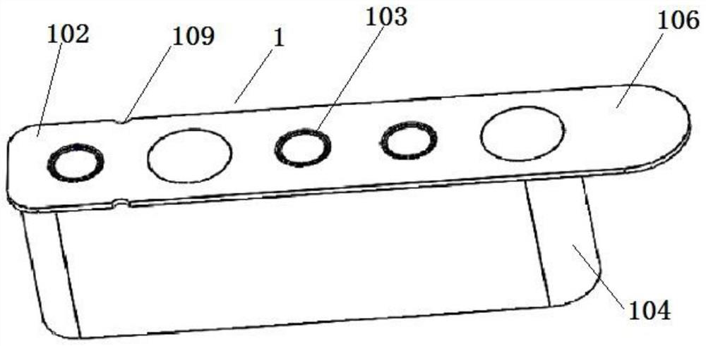
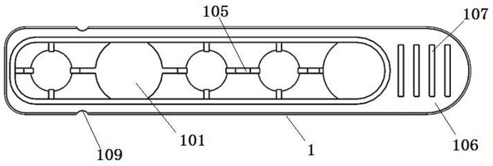
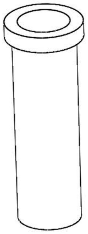
[0053] Embodiment 1: as Figure 1~4 As shown, the five-way cup 1 includes a connecting sleeve 102 and five cup grooves 101, the connecting sleeve 102 is provided with five connecting holes 103 corresponding to the cup grooves 101, and the five cup grooves 101 are respectively connected to the The five connection holes 103 are vertically connected one by one, so that the plurality of cup grooves 101 are independent of each other; the five-way cup 1 also includes a cup sleeve 104, and the cup sleeve 104 surrounds the five cup grooves 101 The outer wall of the connecting sleeve 102 is vertically connected with the connecting sleeve 102; the connecting sleeve 102 also includes several connecting parts 105, and the connecting parts 105 are respectively arranged between the five cup grooves 101 and the cup grooves 101 and the Between the cup sleeves 104; one end of the connecting sleeve 102 extends horizontally with a handle 106; the outer edge of the handle 106 is arc-shaped, and t...
Embodiment 2
[0054] Embodiment 2: as Figure 5-10As shown, the sampling device includes a sampling device body 7, a five-way cup 1, a ball plunger 3 and a driving device 4, and the ball plunger 3 is connected to the sampling device body 7 Above, the driving device 4 drives and controls the movement of the five-unit cup 1; the ball plunger 3 limits the position of the five-unit cup 1; the sampling device also includes a dial device 5, and the dial The hand device 5 includes a second dial 501, a first dial 502 and a connecting rod 503, the second dial 501 and the first dial 502 are respectively arranged at both ends of the connecting rod 503, the first One side of a dial 502 is provided with a dial rotating shaft 506; the connecting rod 503 is connected with a spring 504 through a spring fixing block 505 under the first dial 502, and one end of the spring 504 is connected to the first The dial 502 is in press-fit contact and the other end of the spring 504 is connected with a photocoupler l...
PUM
 Abstract
Description
Claims
Application Information
PatSnap Eureka turns technology decisions into work you can execute. Powered by our Innovation Knowledge Graph, it runs expert workflows across engineering, life sciences, materials and intellectual property. Get your review-ready output in minutes.


