
Display panel and display device

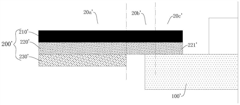
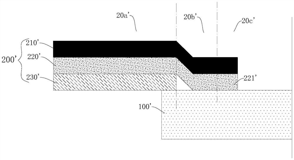
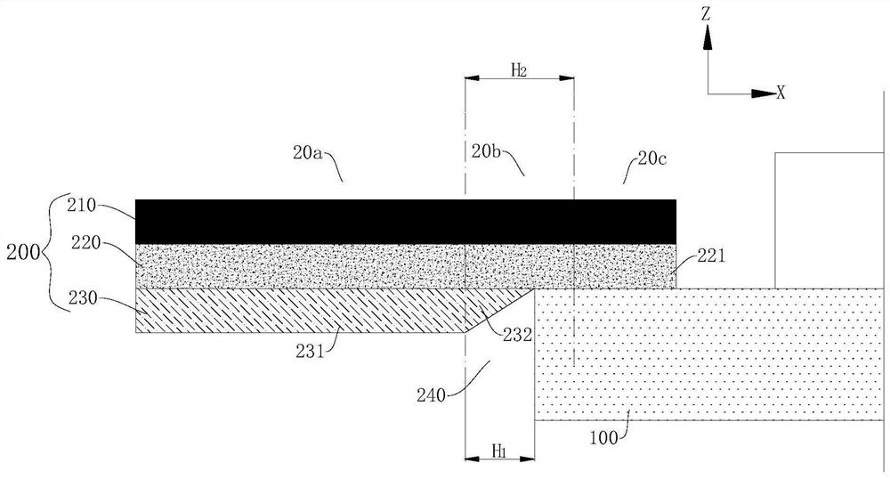
A technology for display panels and substrates, which is used in identification devices, electrical connection of printed components, instruments, etc., can solve problems such as easy damage of metal layer wires, and achieve the effects of preventing bump damage, improving service life and improving yield.

Active Publication Date: 2022-04-29
WUHAN TIANMA MICRO ELECTRONICS CO LTD
View PDF12 Cites 0 Cited by
  • Summary
  • Abstract
  • Description
  • Claims
  • Application Information

AI Technical Summary

Problems solved by technology

[0004] Embodiments of the present invention provide a display panel and a display device, aiming to solve the problem that the wires of the metal layer in the display panel are easily damaged

Method used


Image

  • Display panel and display device
  • Display panel and display device
  • Display panel and display device

Examples


Embodiment Construction

[0020] Various exemplary features and embodiments of the present invention will be described in detail below. In the following detailed description, many specific details are proposed in order to provide a comprehensive understanding of the invention. However, it is obvious to those skilled in the art that the invention can be implemented without some of these specific details. The following description of the embodiments is only to provide a better understanding of the invention by showing an example of the invention. In the drawings and the following description, at least some well-known structures and techniques are not shown in order to avoid unnecessary ambiguity to the invention; Moreover, the size of some structures may be exaggerated for clarity. Further, the features, structures, or characteristics described below may be combined in any suitable manner in one or more embodiments.

[0021] In the description of the invention, it should be noted that unless otherwise specif...


PUM


Abstract

Embodiments of the present invention provide a display panel and a display device. The display panel includes: a flexible circuit board for driving an array substrate, having a main body area, a binding area and a transition area, the transition area is located between the main body area and the binding area, and the flexible circuit board The board includes a stacked substrate, a wiring layer, and an insulating layer. The wiring layer includes metal wires; wherein, the metal wires located in the bonding area are exposed from the insulating layer and overlapped with the driving array substrate for bonding connection. The insulating layer includes a first For the insulating part and the second insulating part, at least part of the first insulating part is located in the main body area, and the second insulating part is located in the transition area, and the average thickness of the first insulating part is greater than the average thickness of the second insulating part. The embodiments of the present invention can increase the service life of the metal wires and improve the yield of the display panel.

Description

technical field [0001] The invention relates to the technical field of display equipment, in particular to a display panel and a display device. Background technology [0002] With the continuous updating of the display, the small-size panel is gradually developing towards light and thin, high screen proportion, ultra narrow border and even no border. In order to increase the screen share of the display device, the metal wire is usually bent to the back of the display device. The display panel usually includes a display area and a non display area located on the peripheral side of the display area. The wiring layer of the non display area is used to arrange and bind flexible circuits. The wiring layer is overlapped on the substrate of the display area. In order to avoid the insulation layer of the wiring layer being overlapped on the substrate, there is a preset distance between the insulation layer and the substrate, which will cause the metal layer of the wiring layer not to be...

Claims


Application Information

Patent Timeline
Patent Type & Authority Patents(China)
IPC IPC(8): G09F9/30H05K1/02H05K1/11
CPCG09F9/301H05K1/028H05K1/11
Inventor 刘海民
Owner WUHAN TIANMA MICRO ELECTRONICS CO LTD
Learn More