High-strength multilayer switch cabinet

A multi-layer switch, high-strength technology, applied in the field of switchgear, can solve the problems of inability to adjust the distance of each layer according to needs, low compressive strength of multi-layer switchgear, damage to electrical components, etc., to avoid deformation, increase strength, improve The effect of external force tolerance

Pending Publication Date: 2020-11-27
江苏中顺电气有限公司
View PDF5 Cites 6 Cited by
  • Summary
  • Abstract
  • Description
  • Claims
  • Application Information

AI Technical Summary

Problems solved by technology

[0002] The switch cabinet is a kind of electrical equipment. The outside line of the switch cabinet first enters the main control switch in the cabinet, and then enters the sub-control switch. Each branch is set according to its needs. The main function of the switch cabinet is to generate, transmit, distribute and In the process of electric energy conversion, open and close, control and protect electrical equipment. Among them, multi-layer switchgear is also widely used as a kind of switch cabinet. Most of the existing multi-layer switch cabinets are fixed and cannot be installed according to needs. Adjusting the distance between layers has low flexibility and inconvenient use. At the same time, some multi-layer switchgears have low compressive strength and poor shock resistance. They are prone to deformation under the action of external forces and cause electrical components inside the cabinet to damage

Method used


Image

  • High-strength multilayer switch cabinet
  • High-strength multilayer switch cabinet
  • High-strength multilayer switch cabinet

Examples


Embodiment Construction

[0023] The following will clearly and completely describe the technical solutions in the embodiments of the present invention with reference to the accompanying drawings in the embodiments of the present invention. Obviously, the described embodiments are only some, not all, embodiments of the present invention. Based on the embodiments of the present invention, all other embodiments obtained by persons of ordinary skill in the art without making creative efforts belong to the protection scope of the present invention.

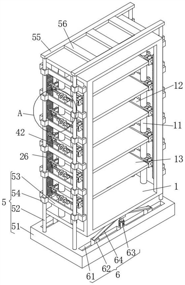
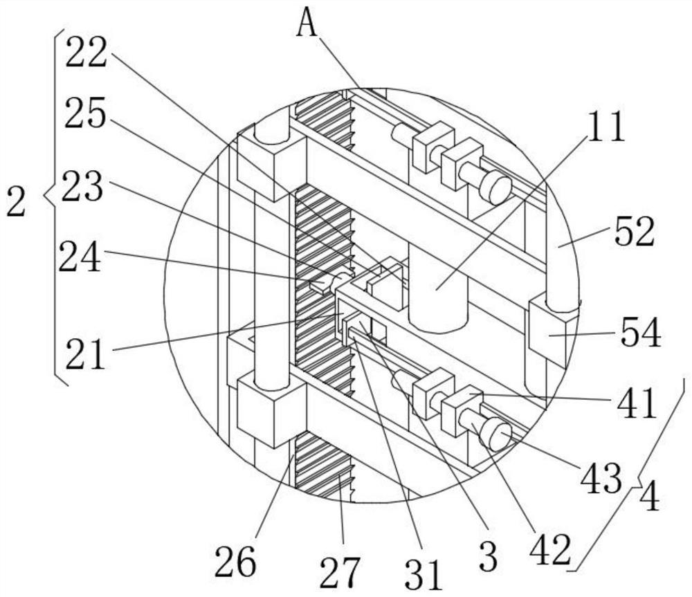
[0024] see Figure 1-3 , the present invention provides a technical solution: a high-strength multi-layer switch cabinet, including a cabinet body 1 and a limit assembly 2;

[0025] Cabinet body 1: There are guide rods 11 symmetrically arranged on both sides, and six movable blocks 12 are evenly movably socketed on the guide rods 11, and laminates 13 are arranged between the corresponding movable blocks 12 on both sides, and cabinet body 1 is provided with Re...


PUM


Abstract

The invention discloses a high-strength multi-layer switch cabinet which comprises a cabinet body and a limiting assembly. Guide rods are symmetrically arranged on the two sides of the cabinet body, movable blocks are movably connected to the guide rods in a sleeving mode, and a layer plate is arranged between the corresponding movable blocks on the two sides. The limiting assembly comprises mounting grooves, a guide groove, a limiting rod, a limiting plate and a baffle. The number of the mounting grooves is two. Two mounting grooves are symmetrically formed in the two ends of the movable block. The guide groove penetrates through the upper and lower surfaces of the mounting groove. One end of the limiting rod penetrates through the side surface of the mounting groove and extends out of the mounting groove. The limiting plate is arranged at one end, outside the mounting groove, of the limiting rod. The baffle is arranged at the end, located in the mounting groove, of the limiting rod.The upper end and the lower end of the baffle are in sliding fit with side faces of the upper side and the lower side of the guide groove correspondingly. A control assembly is arranged on the limiting assembly. According to the high-strength multi-layer switch cabinet, flexible adjustment of the distance between the layers can be achieved according to needs, the strength and the shock resistanceof the cabinet body are improved, and the high-strength multi-layer switch cabinet is high in practicability.

Description

technical field [0001] The invention relates to the technical field of switch cabinets, in particular to a high-strength multi-layer switch cabinet. Background technique [0002] The switch cabinet is a kind of electrical equipment. The outside line of the switch cabinet first enters the main control switch in the cabinet, and then enters the sub-control switch. Each branch is set according to its needs. The main function of the switch cabinet is to generate, transmit, distribute and In the process of electric energy conversion, open and close, control and protect electrical equipment. Among them, multi-layer switchgear is also widely used as a kind of switch cabinet. Most of the existing multi-layer switch cabinets are fixed and cannot be installed according to needs. Adjusting the distance between layers has low flexibility and inconvenient use. At the same time, some multi-layer switchgears have low compressive strength and poor shock resistance. They are prone to deforma...

Claims


Application Information

Patent Timeline
Patent Type & Authority Applications(China)
IPC IPC(8): H02B1/54H02B1/052H02B1/30H02B1/32
CPCH02B1/54H02B1/0523H02B1/30H02B1/32
Inventor 刘洋
Owner 江苏中顺电气有限公司
Why Eureka
Try Eureka