
C-shaped steel forming machine

A forming machine and C-shaped steel technology, applied in other manufacturing equipment/tools, manufacturing tools, etc., can solve the problems of reduced punching accuracy, reduced cutting accuracy, unfavorable steel plate feeding, etc., to achieve improved accuracy, improved stability, improved The effect of production efficiency

Inactive Publication Date: 2020-12-01
济南市鼎冉金属制品有限公司
View PDF14 Cites 3 Cited by
  • Summary
  • Abstract
  • Description
  • Claims
  • Application Information

AI Technical Summary

Problems solved by technology

[0004] 1. After loading the C-shaped steel forming machine, the steel plate needs to be flattened. During the flattening process, the steel plate will be deformed, and this deformation will be transmitted to the steel plate outside the feed end, making the steel plate The stress situation of the steel plate changes, so the position of the steel plate feeding is constantly changing, which is not conducive to the feeding of the steel plate
[0005] 2. Most of the equipment is a fixed structure, especially in the bending part of the steel plate. Due to the needs of different sizes, different C-shaped steels need to be processed, and the fixed structure has certain limitations in use.
[0006] 3. When punching the bent C-shaped steel, because the C-shaped steel is not pre-pressed, when punching, the C-shaped steel suddenly receives an impact force and causes it to shift, reducing the accuracy of punching
[0007] 4. When cutting the C-shaped steel, there is also no precise mold to position the C-shaped steel. When cutting, the C-shaped steel may be displaced, resulting in reduced cutting accuracy or a slope.

Method used


Image

  • C-shaped steel forming machine
  • C-shaped steel forming machine
  • C-shaped steel forming machine

Examples


Embodiment 1

[0054] The embodiment of the present application discloses a C-shaped steel forming machine, which adopts the following technical scheme:

[0055] A C-shaped steel forming machine, refer to figure 1 , including a frame 1000, a guide positioning assembly 2000, a flattening assembly 3000, a side bending assembly 4000, a middle bending assembly 5000, a beading assembly 6000, a punching assembly 7000 and a shearing assembly installed on the frame 1000 in sequence 8000.

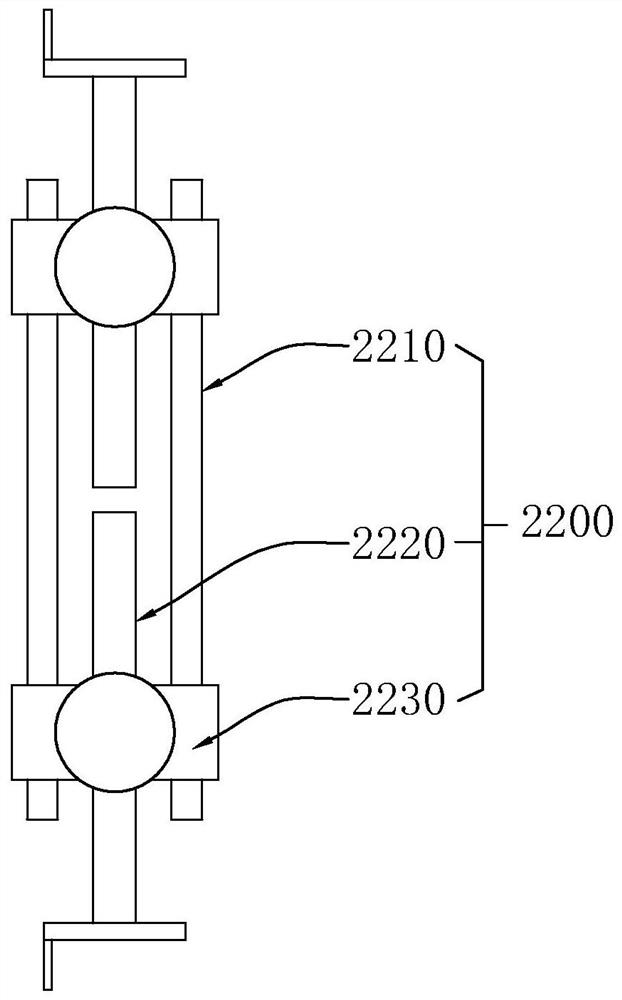
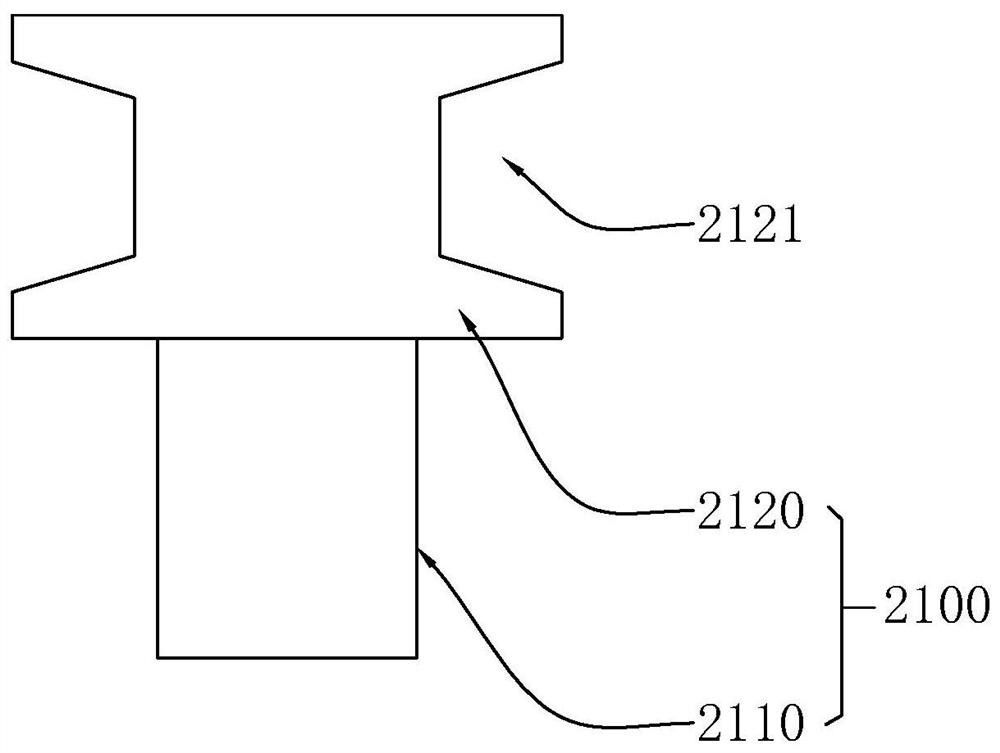
[0056] In this embodiment, a guiding and positioning assembly 2000 is provided on both sides of the flattening assembly 3000, and the guiding and positioning assembly 2000 has at least two opposite guiding and positioning wheels 2100; Guiding and positioning prevents the shift and deformation of the steel plate, improves the stability of the steel plate feeding, and improves the production efficiency; the flattening assembly 3000 includes several groups of pressing rollers 3100 that are rotatably connected to the...


PUM


Abstract

The invention relates to a C-shaped steel forming machine. The C-shaped steel forming machine comprises a rack, and a guiding and positioning assembly, a flattening assembly, a side bending assembly,a middle bending assembly, a ribbing assembly, a punching assembly and a shearing assembly which are arranged on the rack in sequence, the C-shaped steel forming machine has the beneficial effects that the guiding and positioning assembly is used for guiding and positioning a steel plate to enter the flattening assembly, displacement and deformation of the steel plate are prevented, the feeding stability of the steel plate is improved, and the production efficiency is improved. The flattening assembly is mainly used for flattening the steel plate, subsequent bending forming is facilitated, andthe product quality of the C-shaped steel is improved. The C-shaped steel is firstly fixed and then punched through the pre-fixing punching mechanism, the punching precision is improved, then the C-shaped steel is positioned and sheared through the positioning and shearing mechanism, the shearing precision is improved, and the production quality of the C-shaped steel is improved in the whole production process.

Description

technical field [0001] The present application relates to the technical field of steel plate processing equipment, in particular to a C-shaped steel forming machine. Background technique [0002] The C-shaped steel is automatically processed and formed by the C-shaped steel forming machine, and the steel plate is made by feeding, bending, stretching, shearing and other processes. [0003] According to the inventor's understanding, in the relevant technology of C-shaped steel forming machine, there are following problems: [0004] 1. After loading the C-shaped steel forming machine, the steel plate needs to be flattened. During the flattening process, the steel plate will be deformed, and this deformation will be transmitted to the steel plate outside the feed end, making the steel plate The stress situation of the steel plate changes, so the position of the steel plate feeding is constantly changing, which is not conducive to the feeding of the steel plate. [0005] 2. Mos...

Claims


Application Information

Patent Timeline
Patent Type & Authority Applications(China)
IPC IPC(8): B23P23/04
CPCB23P23/04
Inventor 卢迪张磊刘秀丽
Owner 济南市鼎冉金属制品有限公司
Learn More