
Packaging box film corner cutting device and method

A packaging box and corner cutting technology, which is applied in the direction of packaging material feeding device, packaging, transportation packaging, etc., can solve the problems of poor film absorption, easy deformation, film deformation, etc., and achieve the effect of improving adaptability and reducing costs

Inactive Publication Date: 2020-12-01
伍福庆
View PDF6 Cites 0 Cited by
  • Summary
  • Abstract
  • Description
  • Claims
  • Application Information

AI Technical Summary

Problems solved by technology

[0004] The prior art has the following deficiencies: 1. When making a film bag and moving the film, a suction device with a fixed length is used to suck the film, and then the driving device drives the suction device to move to the corresponding station to move the film sucked by the suction device ; and the suction device absorbs the film through vacuum generation, and the degree of bonding between the suction device and the film is required when the vacuum generates suction; when the suction bottom plate in the suction device has poor flatness or the surface of the film is uneven At this time, there will be a certain gap between the suction device and the film, which will destroy the fit between the suction device and the film, and a part of the suction force of the suction device on the film will flow out along the gap, thereby causing the suction device to the film. At the same time, the suction device with a fixed length can only absorb the film that is longer than the suction device; when the film length is short, the suction hole in the suction device that is longer than the film will also be damaged because it is not attached to the film. Leakage, which makes the aspirator less adaptable
2. When stretching the film bag, the forming device first makes the film into a film bag in which the upper and lower films are in contact; then the upper and lower suction plates of the suction device are respectively in contact with the upper and lower sides of the film bag, and the suction device drives the upper and lower suction plates respectively upward and downward. The downward movement separates the upper and lower sides of the film bag in contact with the suction plate; and the film surface has a certain viscosity, when the upper and lower side films of the film bag are in contact, the upper and lower films will be bonded due to the surface viscosity; and The material of the film is soft and it is easy to deform when it is under force. When the upper and lower suction plates of the suction device drive the bonded upper and lower films to separate through suction, the film will be irregular due to the simultaneous suction and irregular adhesion. Deformation; resulting in different degrees of wrinkles in some parts of the film bag when the film bag is stretched, affecting the quality of the film bag
3. When cutting off the excess film at the four corners of the edge-sealed packaging box, the moving mechanism is generally used to move the edge-sealed packaging box to a fixed-sized corner-cutting mold, and then the cutting component action relative to the fixed position of the corner-cutting mold will move the package Excess film is cut off from the four corners of the box; the fixed-size corner-cutting mold can only correspond to one size of the packaging box; when it is necessary to cut the corners of multiple sizes of packaging boxes at the same time, it is necessary to reprocess and replace the molds of different sizes; As a result, the adaptability of the corner cutting device is low, and the mold cost of the corner cutting device is increased

Method used


Image

  • Packaging box film corner cutting device and method
  • Packaging box film corner cutting device and method
  • Packaging box film corner cutting device and method

Examples


Embodiment 1

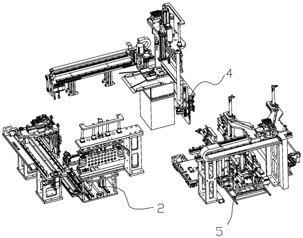
[0036] Such as figure 1 Shown is a box film packaging equipment, which includes a workbench and a film feeding device fixed on the workbench, a film bag forming bag supporting device 2, a box feeding device, an edge sealing device 4 and a corner cutting device 5. The outlet of the film feeding device is connected with the inlet of the film bag forming and supporting device 2, and the outlet of the film bag forming and supporting device 2 is respectively connected with the outlet of the packing box feeding device and the inlet of the edge sealing device The feed port and discharge port of the angle cutting device 5 are respectively connected with the discharge port of the edge sealing device 4 and the blanking station; the film feeding device is used for feeding the film; the film bag forming bag supporting device 2 is used for Form the film and stretch the prepared film bag; the packing box feeding device is used for feeding the packing box; the edge sealing device 4 is used t...


PUM


Abstract

The invention relates to the field of packaging of packaging boxes, in particular to a packaging box film corner cutting device and method. The device comprises a corner cutting feeding mechanism, a corner cutting moving mechanism, a slitting mechanism and a corner cutting discharging mechanism; the input end and the output end of the corner cutting feeding mechanism are connected with the outputend of an edge sealing device and the input end of the corner cutting moving mechanism correspondingly, and the output end of the corner cutting moving mechanism is connected with the input end of theslitting mechanism and the input end of the corner cutting discharging mechanism correspondingly; the output end of the corner cutting discharging mechanism is connected with a discharging opening; the corner cutting feeding mechanism is used for feeding an edge-sealed packaging box; the corner cutting moving mechanism is used for moving the packaging box; the slitting mechanism is used for cutting off redundant films at the four corners of the edge-sealed packaging box; and the corner cutting discharging mechanism is used for discharging the processed packaging box. According to the device,by arranging the slitting mechanism, the adaptability of the packaging box film corner cutting device is improved, and the cost of the corner cutting device is lowered.

Description

technical field [0001] The invention relates to the field of packaging box packaging, in particular to a device and method for cutting corners of a packaging box film. Background technique [0002] Film packaging is mainly a packaging method that wraps the product with a heat-shrinkable film and then heats it so that the film shrinks and wraps the product. For the box film packaging process, it generally includes: hot cutting, pushing the box into the bag, hot sealing, hot cutting four corners and blanking. The film packaging of the packaging box can not only beautify the outer surface of the packaging box, but also protect the mobile phone during the transportation process from the manufacturer to the dealer, preventing damage to the mobile phone during the transportation process. Therefore, for packaging box processing, its film packaging is particularly important. [0003] The State Intellectual Property Office of China has published a publication number of CN208248549U...

Claims


Application Information

Patent Timeline
IPC IPC(8): B65B61/00B65B41/14B65B43/04B65B43/30B65B61/28
CPCB65B41/14B65B43/04B65B43/30B65B61/00B65B61/28
Inventor 伍福庆袁银玲
Owner 伍福庆
Learn More