An electric desalination tank for residual oil dewaxing

An electric desalting and dewaxing technology, applied in the direction of electric/magnetic dehydration/emulsification, cleaning methods and appliances, and electric/magnetic refining, etc., can solve the problems of affecting desalting effect, poor cleaning effect, high-pressure pump power, etc. , to improve the separation efficiency

Active Publication Date: 2021-01-26
DONGYING LIANHE PETROCHEMICAL CO LTD
View PDF9 Cites 0 Cited by
  • Summary
  • Abstract
  • Description
  • Claims
  • Application Information

AI Technical Summary

Problems solved by technology

[0002] After the electric desalting tank desalts and dehydrates the crude oil, the sludge will deposit in the lower part of the water layer at the bottom of the electric desalting tank, and it will accumulate more and more. The insoluble sludge will deposit at the bottom of the electric desalting tank, gradually reducing the volume of the electric desalting tank It affects the normal operation of the electric desalination tank, and also affects the desalination effect. The continuous backwashing operation is not effective in eliminating sludge deposits. Refining, the existing electric desalination tank device cleans its interior by spraying high-pressure water through perforated pipe holes or nozzles. However, this cleaning method consumes a lot of water and increases the follow-up sewage treatment project, which is not convenient for the extraction of crude oil in sewage. In addition, the power of the high-pressure pump required is large, and the power consumption is large. The backwash system on the existing electric desalination tank device increases the flushing range by adding nozzles, but this method will cause the impact force of the water flow to disperse, resulting in poor cleaning effect. Difference

Method used


Image

  • An electric desalination tank for residual oil dewaxing
  • An electric desalination tank for residual oil dewaxing
  • An electric desalination tank for residual oil dewaxing

Examples


Embodiment Construction

[0015] In order to make the purpose, technical solutions and advantages of the embodiments of the present invention clearer, the technical solutions in the embodiments of the present invention will be clearly and completely described below in conjunction with the drawings in the embodiments of the present invention. Obviously, the described embodiments It is a part of embodiments of the present invention, but not all embodiments. Based on the embodiments of the present invention, all other embodiments obtained by persons of ordinary skill in the art without creative efforts fall within the protection scope of the present invention.

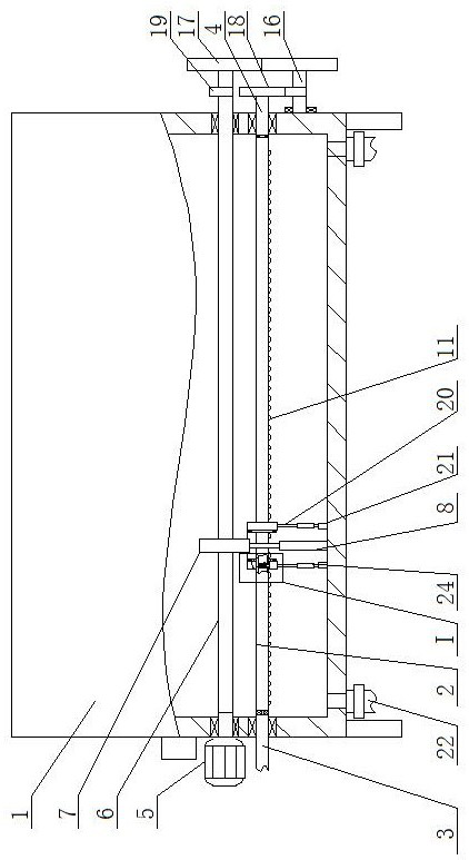
[0016]An electric desalting tank for residual oil dewaxing, as shown in the figure, includes a main body 1 of the electric desalting tank, and supporting legs are fixedly installed on both sides of the outer wall and bottom surface of the main body 1 of the electric desalting tank, and a manhole is arranged on the main body 1 of the electric desalt...


PUM


Abstract

An electric desalting tank for residual oil dewaxing, the invention belongs to the field of crude oil processing equipment, comprising a main body of an electric desalting tank, a square pipe is arranged at the inner bottom of the main body of the electric desalting tank, one end of the square pipe is connected to one end of a high-pressure pipe through a sealed bearing and connected to the The high-pressure pipe runs through one side of the inner wall of the main body of the electric desalination tank and is connected with it through a sealed bearing. The other end of the square pipe is fixedly connected to one end of the first rotating shaft. The mud discharge pipe of the valve and the mud discharge pipe communicate with the main body of the electric desalination tank. This device controls the water spraying position on the square pipe by controlling the position of the square sleeve, which is different from the backwash system on the existing electric desalination tank device. Compared with the method of continuously spraying water from several nozzles, it can effectively reduce water consumption, facilitate the extraction of residual crude oil from sewage, and make it easier for the scraper to scrape out the sludge, thereby improving the cleaning effect.

Description

technical field [0001] The invention belongs to the field of crude oil processing equipment, in particular to an electric desalting tank for residual oil dewaxing. Background technique [0002] After the electric desalting tank desalts and dehydrates the crude oil, the sludge will deposit in the lower part of the water layer at the bottom of the electric desalting tank, and it will accumulate more and more. The insoluble sludge will deposit at the bottom of the electric desalting tank, gradually reducing the volume of the electric desalting tank It affects the normal operation of the electric desalination tank, and also affects the desalination effect. The continuous backwashing operation is not effective in eliminating sludge deposits. Refining, the existing electric desalination tank device cleans its interior by spraying high-pressure water through perforated pipe holes or nozzles. However, this cleaning method consumes a lot of water and increases the follow-up sewage tr...

Claims


Application Information

Patent Timeline
Patent Type & Authority Patents(China)
IPC IPC(8): B08B9/08C10G32/02C10G33/02
CPCC10G32/02C10G33/02
Inventor 齐世森房永涛石允起刘大禄李彬彬王新岐
Owner DONGYING LIANHE PETROCHEMICAL CO LTD
Why Eureka
Try Eureka