Offshore spilled oil recovery device

A recovery device and technology for oil spills at sea, applied in general water supply conservation, water conservancy projects, and open-air water surface cleaning, etc., can solve the problems of slow recovery speed and limited application environment, and achieve fast recovery speed, wide application environment, continuous The effect of strong work ability

Active Publication Date: 2020-12-01
西安美术学院
View PDF4 Cites 6 Cited by
  • Summary
  • Abstract
  • Description
  • Claims
  • Application Information

AI Technical Summary

Problems solved by technology

[0004] The purpose of the present invention is to solve the disadvantages of limited application environment a

Method used


Image

  • Offshore spilled oil recovery device
  • Offshore spilled oil recovery device
  • Offshore spilled oil recovery device

Examples


Embodiment 1

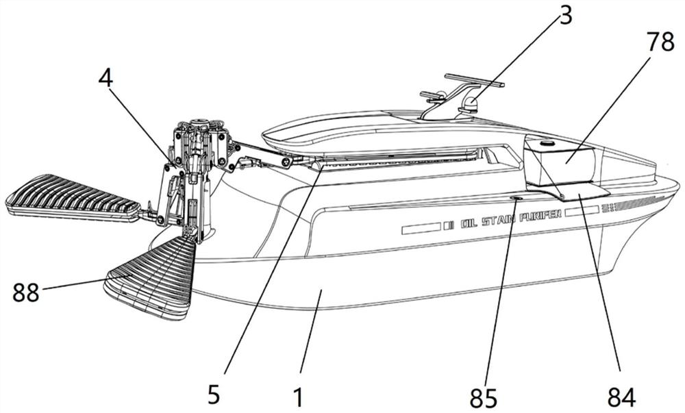
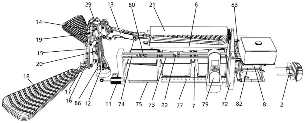
[0045] Such as Figure 1-Figure 9 As shown, a marine oil spill recovery device includes a hull 1 and a control unit located on the hull 1, a drive unit 2, a monitoring and navigation unit 3, an oil suction unit 4, an oil squeeze unit 5, an oil storage unit 6, and an oil packaging unit 7 and oil product transfer unit 8.

[0046] The control unit is connected with the drive unit 2, the monitoring and navigation unit 3, the oil suction unit 4, the oil squeeze unit 5, the oil storage unit 6, the oil product dispensing unit 7 and the oil product transfer unit 8, and the existing controller is used to control each unit The action of driving unit 2 is located at the stern, used to drive the hull 1 to run on the sea surface, including engine (not shown in the hull), propeller 89 and split rudder 90; monitoring and navigation unit 3 is composed of monitoring detector and navigation radar , located on the top of the hull 1, used to guide the hull 1 to the oil spill area and plan the oi...

Embodiment 2

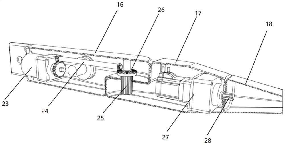
[0055] Such as Figure 9-Figure 11 As shown, the difference between the second embodiment and the first embodiment is that the structures or positions of the oil suction unit 4 , the oil squeeze unit 5 and the oil storage unit 6 are different. details as follows:

[0056] The oil suction unit 4 includes a lifting support column 48 , a second support frame 49 , a fifth motor 50 , a horizontal central shaft (not shown in the figure), a second support shell 52 and two oil suction plates 53 . The lifting support column 48 is arranged on the hull 1; the fifth motor 50 is installed on the lifting support column 48 through the second support frame 49, and its output is connected with the horizontal central axis to drive the horizontal central axis to rotate; the oil-absorbing plate 53 includes a support frame 54 and oil-absorbing sponge 88; the support frame 54 includes a rectangular support base plate 55 and four support side plates that are respectively connected with the four sid...


PUM


Abstract

The invention provides an offshore spilled oil recovery device which solves the problems that an existing spilled oil recovery device is limited in application environment and low in recovery speed. The offshore spilled oil recovery device comprises a ship body and further comprises an oil adsorption unit, an oil extrusion unit, an oil storage unit, an oil product split charging unit and an oil product transfer unit which are located on the ship body, and the control unit is connected with the oil adsorption unit, the oil extrusion unit, the oil storage unit, the oil product split charging unit and the oil product transfer unit. The oil extrusion unit is used for extruding spilled oil adsorbed by the oil adsorption unit to the oil storage unit; the oil product split charging unit is used for split charging of spilled oil in the oil storage unit; and the oil product transfer unit is used for transferring split-charged oil products out of the ship body.

Description

technical field [0001] The invention belongs to waste oil treatment equipment, in particular to a marine oil spill recovery device. Background technique [0002] In recent years, the petroleum industry has developed rapidly. As an important energy material and chemical raw material, petroleum has become increasingly important to the national economy. At the same time, the environmental hazards caused by petroleum have become increasingly prominent. As the main transportation mode of oil, marine transportation, oil spill accidents occur from time to time, mainly through the following four ways: 1) oil tanker accident; 2) drilling platform explosion; 3) oil pipeline leakage; 4) man-made discharge; There are nearly one million tons of oil discharged into the ocean due to oil transportation, and oil spill pollution has become one of the major sources of ocean pollution. The density of crude oil is lower than that of seawater, and it is easy to weather. Under the impact of sea w...

Claims


Application Information

Patent Timeline
IPC IPC(8): E02B15/04E02B15/10
CPCE02B15/04E02B15/041E02B15/045E02B15/046E02B15/10E02B15/101Y02A20/204
Inventor 路鹏王亦林周濛
Owner 西安美术学院
Why Eureka
Try Eureka