Flood prevention device for transformer substation

A technology for flood control devices and substations, applied in water supply devices, grease/oily substance/floating matter removal devices, water/sludge/sewage treatment, etc. It can solve problems such as water pump damage, easy suction of debris, and difficulty in handling. Achieve the effect of convenient transportation and ensure pumping efficiency

Inactive Publication Date: 2020-12-01
国网河南省电力公司南召县供电公司
View PDF8 Cites 2 Cited by
  • Summary
  • Abstract
  • Description
  • Claims
  • Application Information

AI Technical Summary

Problems solved by technology

Long-term immersion of cables in water will corrode the insulation sheath and reduce the insulation, threatening the safe operation of the power grid
At present, it is mainly used to manually carry the water pump to the water accumulation, discharge most of the accumulation water, and then clean it with a mop and other tools. The weight of the water pump is heavy and it is difficult to carry; If it is covered by objects, it will reduce the water absorption efficiency and damage the internal motor
[0003] The Chinese utility model patent whose publication number is CN210637200U discloses a pump for farmland water conservancy irrigation, including a water pump box, a base plate, a moving plate and a water pump, the top of the base plate is fixedly connected with the bottom of the water pump by installing a fixed plate, and the The surface is covered with a water pump box, the top of the water pump is fixed with a control panel, the control panel is fixed with a start switch, and the top of the control panel is provided with one end of the top of the water pump box, and the other end of the top of the water pump box is provided with a suction port. There is a drain port on one side of the water pump box. The water pump port and the water drain port are respectively connected with the water inlet and water outlet of the water pump. They are moved by moving wheels to facilitate the movement of the water pump. However, there is no filter screen at the water inlet of the water pump. When the water pump pumps water, it is easy to draw in sundries and cause damage to the water pump

Method used


Image

  • Flood prevention device for transformer substation
  • Flood prevention device for transformer substation
  • Flood prevention device for transformer substation

Examples


Embodiment 1

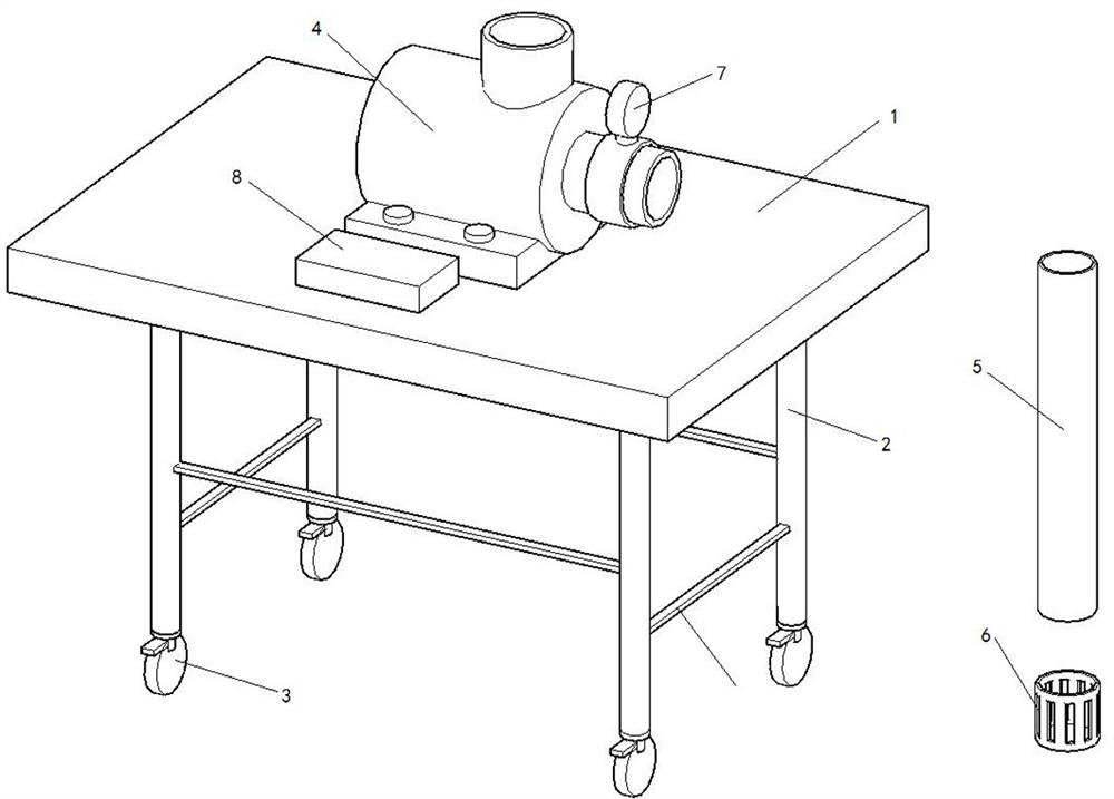
[0028] Such as figure 1 Shown is the first embodiment of the present invention, the vehicle frame includes a top plate 1 and four legs 2 welded and fixed below the top plate 1, and a universal brake wheel 3 is installed on the bottom end surface of the legs 2;

[0029] The suction pump 4 is fixedly installed on the top plate 1 by bolts. The suction pump 4 is provided with a suction port and a water outlet. It is a shell-shaped structure with hollow sides, and the inner peripheral surface of the top of the filter cover 6 is fixed on the outer peripheral surface of the bottom end of the suction pipe 5 by means of glue or the like;

[0030] Flow meter 7, flow meter 7 is installed on the suction port of water pump 4, is used for monitoring the water flow rate that draws out;

[0031] PLC8 is installed on the top plate 1, the flow meter 7 is electrically connected to the input end of PLC8, and the motor of the water pump 4 is electrically connected to the output end of PLC8.

[0...

Embodiment 2

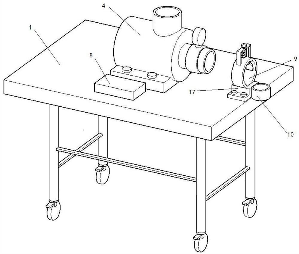
[0034] Such as Figure 2-4 Shown is a schematic structural diagram of the second embodiment of the present invention. The difference between this embodiment and the first embodiment is that the side of the top plate 1 is provided with a limit assembly that restricts the bottom end of the suction pipe 5 to be perpendicular to the ground, and the limit assembly includes a limit ring The first 9 and the limit ring two 10, the limit ring one 9 and the limit ring two 10 are both round shell-shaped structures with openings at both ends, and the limit ring one 9 is fixedly installed on the top surface of the fixed frame 17 by means of glue or the like , the limit ring two 10 is fixedly installed on the side of the fixed frame 17 by means of viscose, etc., the fixed frame 17 is fixedly installed on the top plate 1 by bolts, the limit ring two 10 protrudes from the top plate 1 completely, and one end of the suction pipe 5 is connected to the top plate 1. After the water outlet is conne...

Embodiment 3

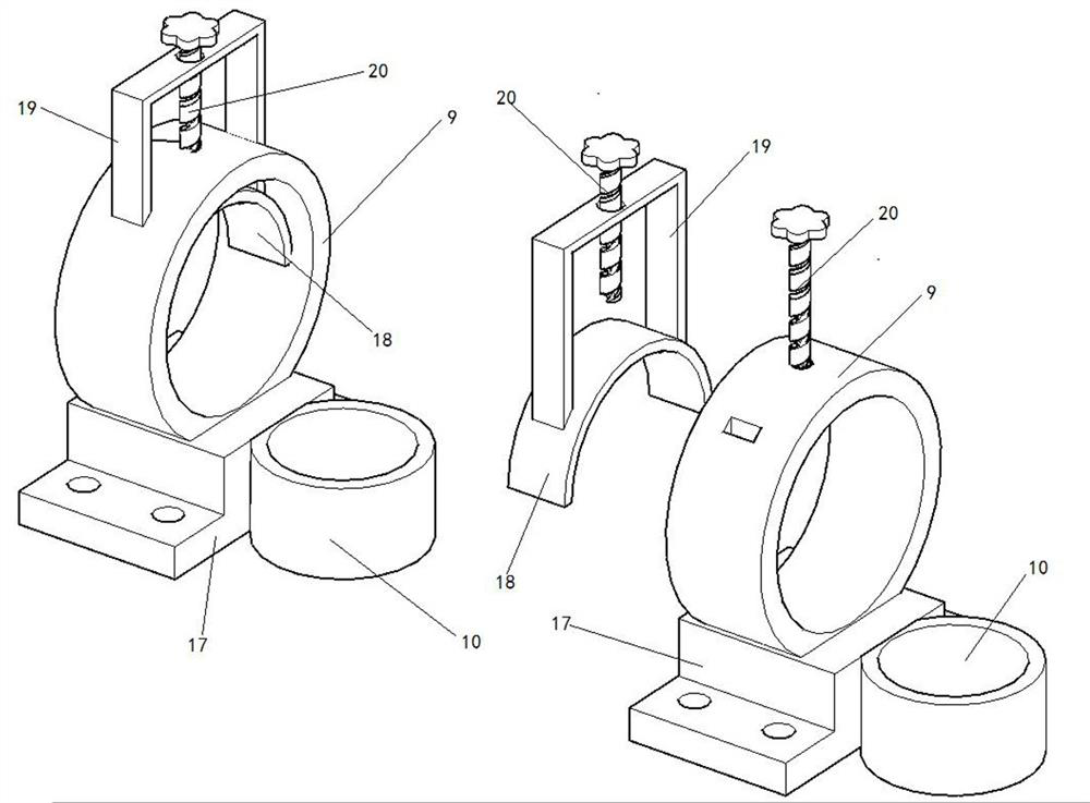
[0037] Such as Figure 4-5Shown is the third embodiment of the present invention, the difference between the present embodiment and the first embodiment is that the top plate 1 is provided with a drive assembly that drives the limit ring one 9 and the limit ring two 10 to be close to or away from the side of the top plate 1, and drives The assembly includes an electric push rod 12, and the accommodating cavity 13 for accommodating the electric push rod 12 is machined on the top plate 1 through a lathe. The longitudinal section is larger than the longitudinal section of the accommodating cavity 13, and the fixing plate 15 is detachably connected to the top plate 1 by bolts. The end of the telescopic end of the electric push rod 12 is fixedly connected to the push plate 14 matched with the accommodating cavity 13 through glue, the limit ring one 9 and the limit ring two 10 are arranged on the push plate 14 and are detachably connected with the push plate 14, The connection meth...


PUM


Abstract

The invention discloses a flood prevention device for a transformer substation. The flood prevention device comprises a vehicle frame, a water pump, a flowmeter and a PLC; the vehicle frame comprisesa top plate and four supporting legs arranged below the top plate, and universal brake wheels are arranged on the bottom end faces of the supporting legs; the water pump is arranged on the top plate,a water pumping port and a water outlet are formed in the water pump, the water pumping port is connected with a water pumping pipe, and a filter cover is arranged at the end of the water pumping pipe; the flowmeter is arranged on the water pumping port and used for monitoring the flow of pumped water; and the PLC is installed on the top plate, the flowmeter is electrically connected with an inputend of the PLC, and a motor of the water pump is electrically connected with an output end of the PLC, such that the water suction pump is convenient to carry, workers can be reminded to clean a filter screen in time during water pumping, and the water pumping efficiency is guaranteed.

Description

technical field [0001] The invention relates to the technical field of substation waterproofing, in particular to a flood prevention device for a substation. Background technique [0002] There is a lot of rain in summer, and some low-lying areas inside the substation are prone to poor drainage and serious water accumulation. Cables soaked in water for a long time will corrode the insulation sheath and reduce the insulation, threatening the safe operation of the power grid. At present, it is mainly used to manually carry the water pump to the water accumulation, discharge most of the accumulation water, and then clean it with a mop and other tools. The weight of the water pump is heavy and it is difficult to carry; If it is covered by objects, the water absorption efficiency will be reduced and the internal motor will be damaged. [0003] The Chinese utility model patent whose publication number is CN210637200U discloses a pump for farmland water conservancy irrigation, in...

Claims


Application Information

Patent Timeline
Patent Type & Authority Applications(China)
IPC IPC(8): E03F5/22E03F3/04E03F5/14
CPCE03F3/04E03F5/14E03F5/22E03F2201/20
Inventor 李勇刘跃宗杨秋月张宇李涵崔铭阳温志中姬翔杨嘉梁
Owner 国网河南省电力公司南召县供电公司
Why Eureka
Try Eureka