Plastering device and plastering robot

A technology of plastering board and body, which is applied in the direction of construction and building structure, can solve the problems of inability to plaster the whole wall and low plastering efficiency, and achieves the improvement of plastering efficiency, good plastering quality and high plastering efficiency. Effect

Active Publication Date: 2020-12-01
GUANGDONG BOZHILIN ROBOT CO LTD
View PDF8 Cites 3 Cited by
  • Summary
  • Abstract
  • Description
  • Claims
  • Application Information

AI Technical Summary

Problems solved by technology

For this reason, the present invention proposes a plastering device, which has high plastering efficiency and good plastering quality, and solves the problem that the plastering device in the prior art cannot plaster the entire wall at one time. inefficient technical issues

Method used


Image

  • Plastering device and plastering robot
  • Plastering device and plastering robot
  • Plastering device and plastering robot

Examples


Embodiment 1

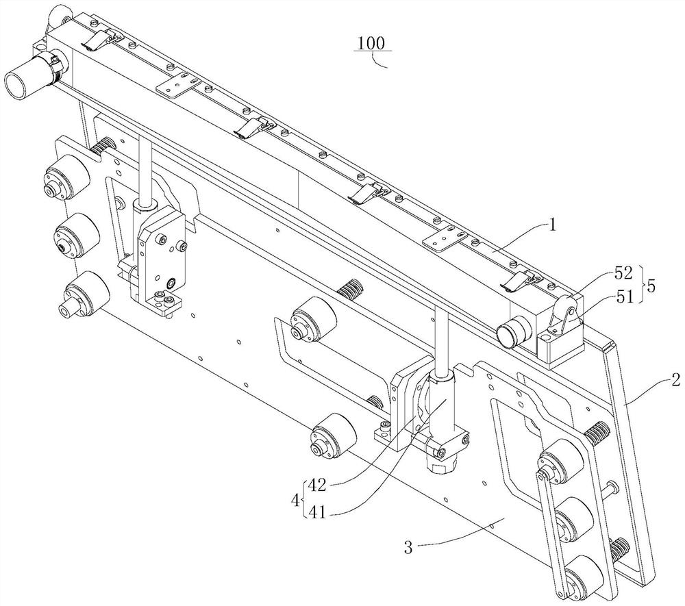
[0156] A plastering device 100, such as figure 1 As shown, it includes: a plastering frame 3, a plastering board 2, a cloth mechanism 1 and an avoidance mechanism 4.

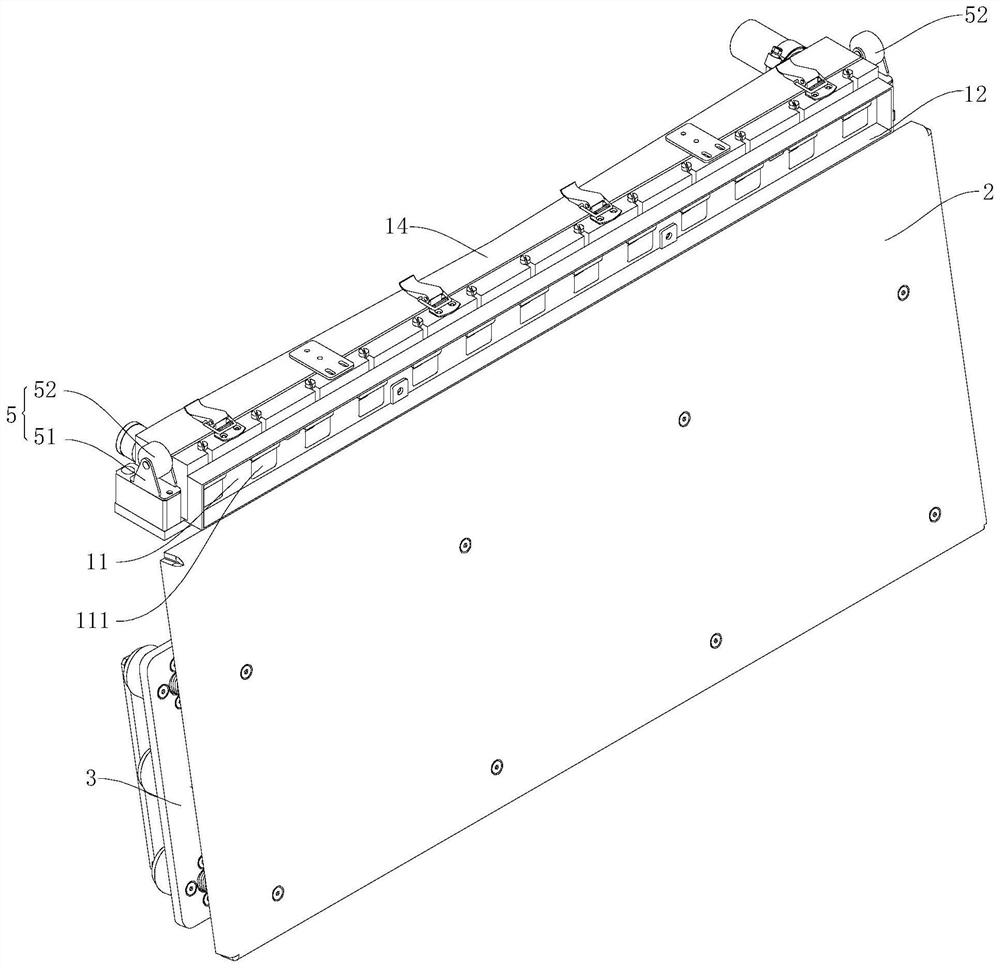
[0157] Among them, such as figure 1 As shown, plastering board 2 is connected on plastering frame 3, and is positioned at the front of plastering frame 3.

[0158] The distributing mechanism 1 transports the mortar to the front of the plastering board 2 , and the distributing mechanism 1 has a distributing position above the upper end of the plastering board 2 and an avoidance position below the upper end of the plastering board 2 .

[0159] Avoidance mechanism 4 is rotatably installed on the plastering frame 3, as figure 1 As shown, the distribution mechanism 1 is installed on the avoidance mechanism 4, and the avoidance mechanism 4 can drive the distribution mechanism 1 to move between the distribution position and the avoidance position.

Embodiment 2

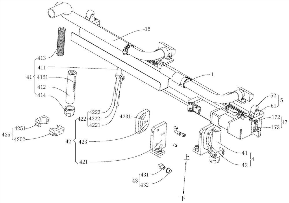
[0161] A kind of plastering device 100, different from Embodiment 1, on the basis of Embodiment 1, such as figure 1 , figure 2 and Figure 4 As shown, the avoidance mechanism 4 includes a swing rod assembly 41 , a guide assembly 42 and a drive assembly 5 .

[0162] Among them, such as figure 1 As shown, one end of the swing rod assembly 41 is rotationally connected with the plastering frame 3 through a rotating member 43, and the other end of the swing rod assembly 41 is fixedly connected with the cloth mechanism 1, as figure 2 As shown, the swing rod assembly 41 is provided with a sliding portion 422 .

[0163] The guide assembly 42 is installed on the plastering frame 3 , the guide assembly 42 is provided with an arc-shaped first guide groove 4231 , and the sliding part 422 can slide along the first guide groove 4231 .

[0164] The driving assembly 5 can drive the swing rod assembly 41 to move from the cloth position to the avoidance position.

[0165] Such as figur...

Embodiment 3

[0167] A kind of plastering device 100, different from Embodiment 2, on the basis of Embodiment 2, such as figure 2 As shown, the swing rod assembly 41 includes a sleeve 412 and a swing rod 411 .

[0168] Wherein, the bottom of sleeve 412 is rotatably connected with plastering frame 3 by rotating member 43, as figure 2 As shown, the outer peripheral wall of the sleeve 412 defines a second guide groove 4121 .

[0169] The swing rod 411 is slidably installed in the sleeve 412 , and one end of the swing rod 411 protrudes from the top of the sleeve 412 and is fixedly connected with the cloth mechanism 1 . Such as figure 2 As shown, the sliding part 422 is installed on the outer peripheral part of the swing rod 411, and extends out of the sleeve 412 from the second guide groove 4121. When the cloth mechanism 1 moves from the cloth position to the avoidance position, the distance between the sliding part 422 and the center of the rotating part 43 The distance gradually decreas...


PUM


Abstract

The invention discloses a plastering device and a plastering robot, wherein the plastering device comprises a plastering frame, a plastering plate, a material distribution mechanism and an avoidance mechanism. The plastering plate is mounted on the plastering frame and positioned in front of the plastering frame; the material distribution mechanism conveys mortar to the front of the plastering plate; and the material distribution mechanism is provided with a material distribution position located above the upper end of the plastering plate and an avoidance position located below the upper endof the plastering plate, the avoidance mechanism is rotatably installed on the plastering frame, the material distribution mechanism is installed on the avoidance mechanism, and the avoidance mechanism is capable of driving the material distribution mechanism to move between the material distribution position and the avoidance position. According to the plastering device, when the material distribution mechanism is located at the material distribution position and the plastering plate cannot continue to move upwards for plastering, the avoidance mechanism is capable of driving the material distribution mechanism to rotate relative to the plastering plate and contract downwards at the same time, so that the material distribution mechanism is switched to the avoidance position, the plastering plate is incapable of continuing to move upwards, the whole building is plastered continuously, the plastering quality is good, and the plastering efficiency is high.

Description

technical field [0001] The invention belongs to the technical field of building decoration, in particular to a plastering device and a plastering robot. Background technique [0002] Plastering, in the construction industry, usually refers to the process of applying lime mortar, mixed mortar, polymer water mortar, hemp knife ash, paper stick ash and thermal insulation mortar particles to the surface of the building. A good plastering process can make The surface of the building is smoother, the aesthetics of the building is increased, and the sound insulation and heat insulation performance of the building can be improved. [0003] However, the traditional plastering work of buildings mainly relies on manual operation. Manual plastering is not only labor-intensive, but also has low plastering efficiency and poor plastering quality. [0004] With the development of the mechanization process, it has become a trend to use machines instead of manual plastering on the surface of...

Claims


Application Information

Patent Timeline
Patent Type & Authority Applications(China)
IPC IPC(8): E04F21/08
CPCE04F21/08
Inventor 唐文相宋涛谢军谭晓勤
Owner GUANGDONG BOZHILIN ROBOT CO LTD
Why Eureka
Try Eureka