

Buffering mechanism of hydraulic machine
A buffer mechanism and hydraulic press technology, applied in the direction of presses, mechanical equipment, springs/shock absorbers, etc., can solve the problems of long pull rods, workbench impacts, etc., and achieve the effect of reducing the impact and stabilizing the flow of liquid
- Summary
- Abstract
- Description
- Claims
- Application Information
AI Technical Summary
Problems solved by technology
Method used
Image

Examples
Embodiment 1
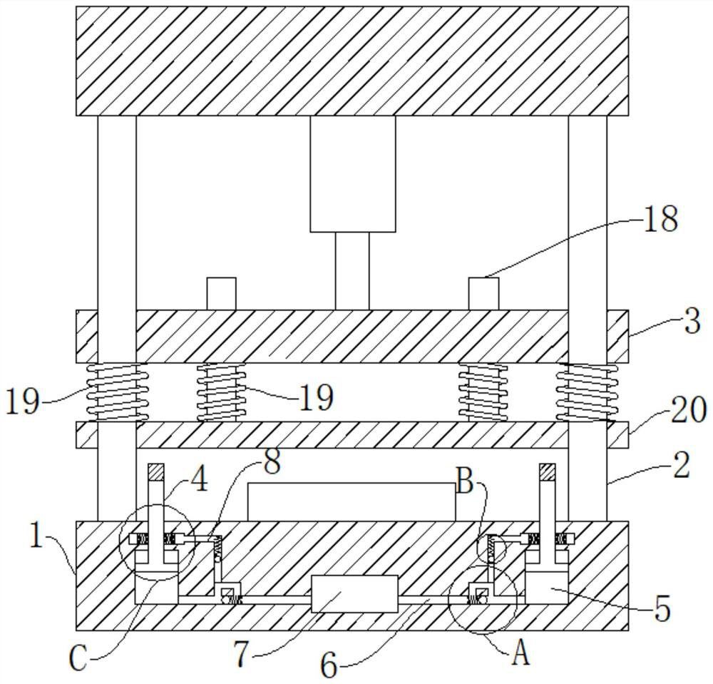
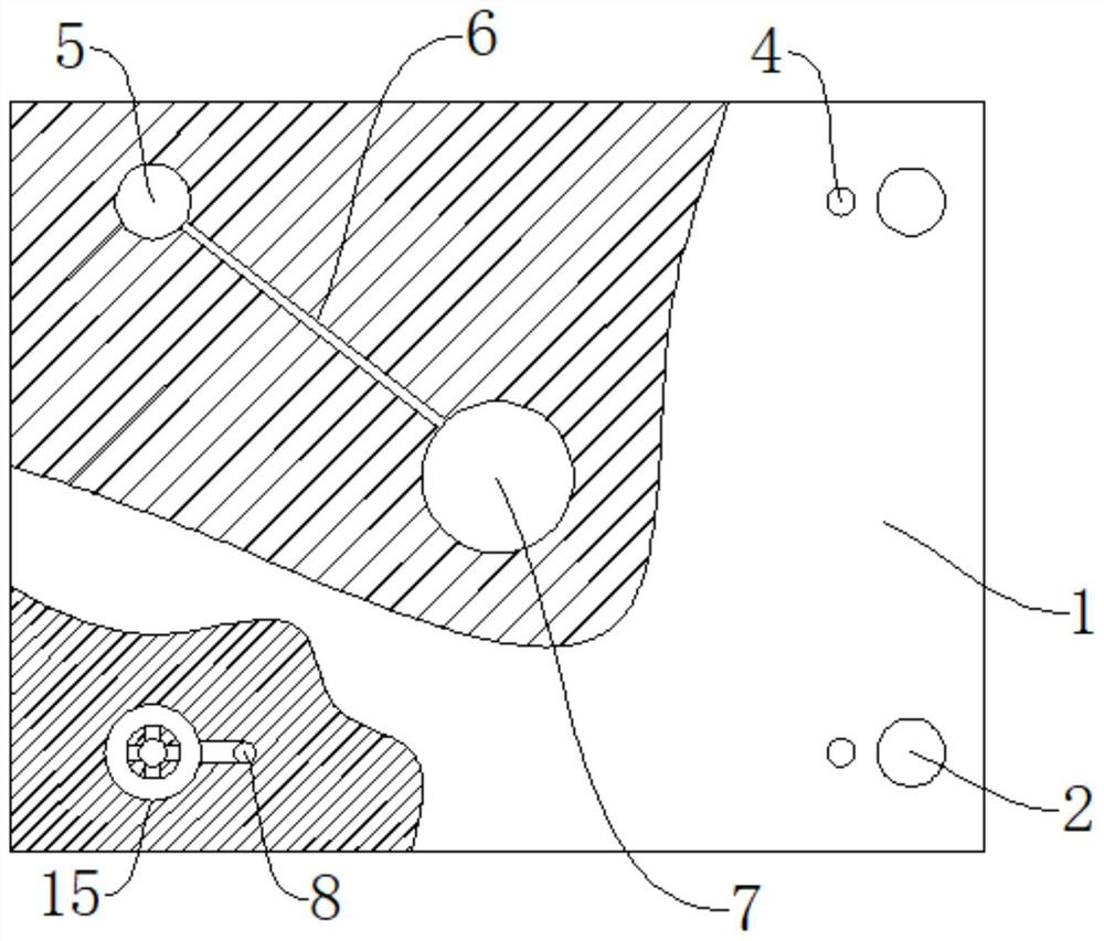
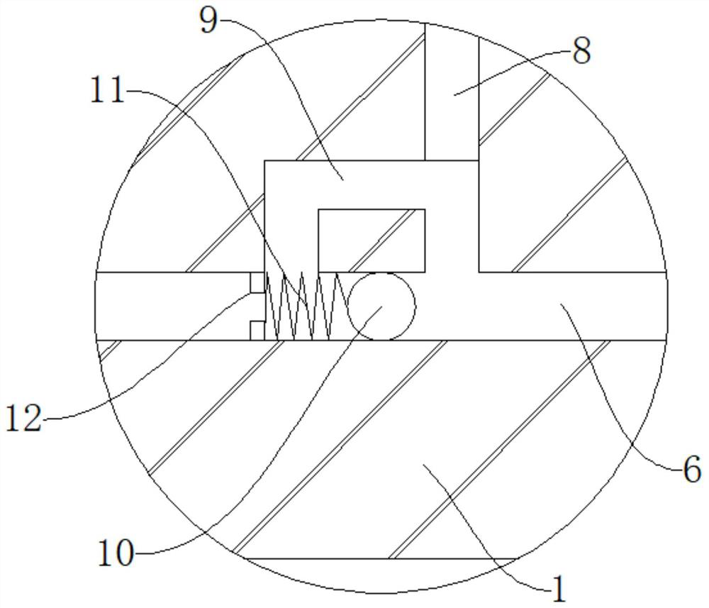
[0028] refer to Figure 1-5 , a hydraulic press buffer mechanism, including a machine base 1, a support column 2, a slide plate 3, the support column 2 is fixedly connected to the upper end of the machine base 1, the slide plate 3 is slidably connected to the support column 2, and multiple groups of liquid tanks 5 are arranged in the machine base 1 , the support rod 4 is slidably connected in the liquid tank 5, the base 1 is provided with a liquid storage chamber 7, and a plurality of groups of liquid pipes 6 are connected to the liquid storage chamber 7, and the end of the liquid pipe 6 far away from the liquid storage chamber 7 is connected to the liquid tank 5 connected, the liquid pipe 6 is connected with a connecting pipe 9, the liquid pipe 6 is slidingly connected with a first stop ball 10, and the end of the liquid pipe 6 close to the connecting pipe 9 is fixedly connected with a stopper 12, and the stopper 12 and the first stopper A first spring 11 is arranged between ...
Embodiment 2
[0032] refer to Figure 1-5 , a hydraulic press buffer mechanism, which is basically the same as that of Embodiment 1, furthermore: the connecting pipe 9 is connected with a liquid inlet pipe 8, the upper end of the liquid tank 5 is provided with an annular groove 15, and a clamp block 16 is slidably connected in the annular groove 15 , the clamp block 16 is attached to the support rod 4, the end of the liquid inlet pipe 8 away from the connecting pipe 9 is connected to the annular groove 15, the second stop ball 13 is slidably connected to the liquid inlet pipe 8, and the second stop ball 13 is fixedly connected There is a second spring 14, and the end of the second spring 14 away from the second stop ball 13 is fixedly connected with the liquid inlet pipe 8, so as to further ensure the support stability of the support rod.
Embodiment 3
[0034] refer to Figure 1-5 , a buffer mechanism for a hydraulic press, which is basically the same as in Embodiment 1, furthermore: a pair of clamping blocks 16 are slidably connected in the annular groove 15, and a third spring 17 is fixedly connected between the pair of clamping blocks 16, wherein A clip 16 is attached to the support rod 4. When the third spring 17 is compressed, under the action of the elastic force of the third spring 17, the clip 16 close to the support rod 4 is closely attached to the support rod 4, further play a buffer role.
PUM
 Abstract
Description
Claims
Application Information