Auxiliary power take-off transmission and agricultural machine

A technology of auxiliary power and power output shaft, which is applied to agricultural vehicles, transportation and packaging, vehicle gearboxes, etc., can solve the problems of high consumption and achieve the effect of simple method cost and smooth switching

Pending Publication Date: 2020-12-01
ZF FIEDRICHSHAFEN AG
View PDF1 Cites 0 Cited by
  • Summary
  • Abstract
  • Description
  • Claims
  • Application Information

AI Technical Summary

Problems solved by technology

[0004] However, known PTO transmissions or auxiliary PTO transmissions are currently disadvantageous because they are relatively expensive to produce

Method used


Image

  • Auxiliary power take-off transmission and agricultural machine

Examples


Embodiment Construction

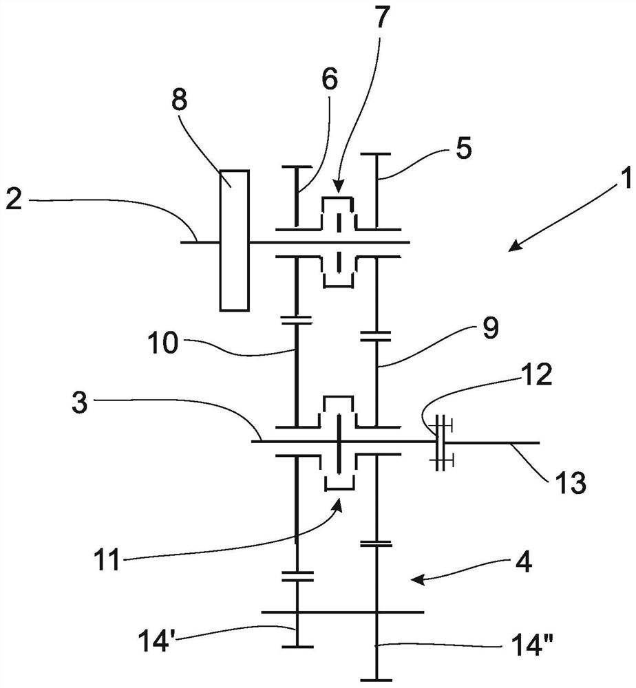
[0025] figure 1 A possible design method according to the auxiliary power output transmission 1 according to the present invention is shown, and the auxiliary power output transmission includes a drive shaft 2, a driven shaft 3, and a positive gear 4 formed as a double forward gear 4. According to an example, two driving idlers 5 and 6 are disposed on the drive shaft 2, which can be coupled to the drive shaft 2 in the drive shaft 2 by the shifting element 7 which is also arranged on the drive shaft 2. The axis is separated. The shifting element 7 is assigned to the drive idler 5 and 6, and can form three different states according to the example, that is, the state of driving the idler 5 and the drive shaft 2 in the driving area; driving the idler 6 and the drive shaft 2 In the driving area; Here, the shifting element 7 is formed to be unable power shifting. Similarly, the main switching element 8 is disposed on the drive shaft 2, by means of manipulating the main shifting elemen...


PUM


Abstract

The invention relates to an auxiliary power take-off transmission (1) for a motor vehicle. The transmission comprises a drive shaft and a driven shaft, wherein a plurality of drive idler wheels and atleast one shift element assigned to the plurality of drive idler wheels are arranged on the drive shaft, at least one shifting element of the plurality of drive idler wheels is assigned by means of an actuation, the respective individual drive idler can be drivingly coupled to or decoupled from the drive shaft, and a plurality of driven idler wheels and at least one shifting element assigned to the plurality of driven idler wheels are arranged on the driven shaft. By means of at least one shifting element assigned to a plurality of output idler wheels, a respective individual output idler wheel can be drivingly coupled to the output shaft or drivingly decoupled from the output shaft, and a respective drive idler wheel is engaged with the respective output idler wheel. A multi-spur gear isalso included, the multi-spur gear being in engagement with the at least two driven idler wheels. The invention also relates to a corresponding agricultural machine.

Description

Technical field [0001] The present invention relates to an auxiliary output transmission power of the preamble of claim 1 and an agricultural work machine according to claim. Background technique [0002] The output shaft of the transmission, in particular for agricultural work machine known in the prior art, which enables the transmission output shaft driving the work tool may be coupled on the work machine can be driven. Examples of such work tools may be driven, for example, a lawn mower, bale baler or fertilizer. Conventionally, a power transmission having an output shaft gear stage, the speed gear stage and outputs the rotation speed of the output shaft of the drive unit of the work machine can be placed in a plurality of adjustable proportional switchable. [0003] In this regard, DE 10 2011 084 623 A1 describes an auxiliary power take-off output shaft speed transmission as a form of transmission, wherein the drive shaft may be by a plurality of intermediate gear stages and...

Claims


Application Information

Patent Timeline
Patent Type & Authority Applications(China)
IPC IPC(8): F16H3/20F16H57/023F16H63/30
CPCF16H3/20F16H57/023F16H63/30F16H2200/0043B60Y2200/22B60K17/08B60K17/28F16H2200/0004F16H2003/0826F16H3/093
Inventor C·鲍尔
Owner ZF FIEDRICHSHAFEN AG
Why Eureka
Try Eureka