
Fan structure of grain drying machine, and grain drying machine

A grain dryer and fan technology, applied in the direction of drying solid materials, dryers, drying gas arrangement, etc., can solve the problems of general flexibility and the inability to adjust the fan blowing angle, so as to ensure the service life and avoid heat loss , Improve the effect of heat insulation

Active Publication Date: 2020-12-01
山西莲芯硒美农业科技开发有限公司
View PDF11 Cites 0 Cited by
  • Summary
  • Abstract
  • Description
  • Claims
  • Application Information

AI Technical Summary

Problems solved by technology

[0003] However, the fan blowing angle of the current grain dryer cannot be adjusted, and the flexibility is average, so it is necessary to improve

Method used


Image

  • Fan structure of grain drying machine, and grain drying machine
  • Fan structure of grain drying machine, and grain drying machine
  • Fan structure of grain drying machine, and grain drying machine

Examples


Embodiment 1

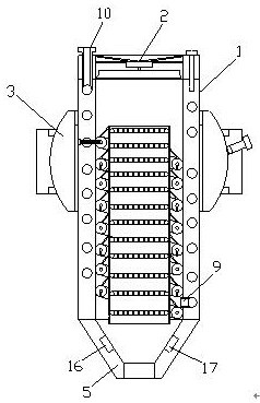
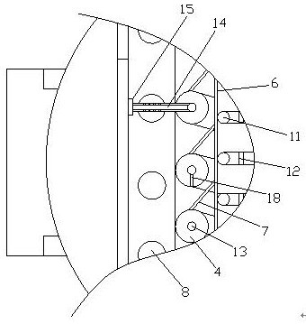
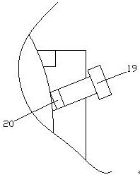
[0026] Such as Figure 1-3 As shown, a fan structure of a grain dryer includes a heat-insulating air duct 1, a fan 2 and a joint bearing 3. An electric heating iron 4 is arranged inside the heat-insulating air duct 1, and the electric heating iron 4 is arranged in a spiral shape. The electric heating iron 4 is in close contact with the inner pipe wall of the heat-insulating air pipe 1, the end of the heat-insulating air pipe 1 is fixedly connected with the fan 2, and the other end of the heat-insulating air pipe 1 is provided with a duckbill nozzle 5, The electric heating iron 4 is fixedly connected with the heat-insulating air pipe 1, and the heat-insulating air pipe 1 is provided with a heat exchange tube 6, and the heat exchange pipe 6 is inserted into the area where the electric heating iron 4 is wound. 6 and the electric heating iron 4 are provided with a heat conduction rod 7, and the two ends of the heat conduction rod 7 are respectively welded to the heat exchange tube...

Embodiment 2

[0029] Such as Figure 1-3 As shown, a fan structure of a grain dryer includes a heat-insulating air duct 1, a fan 2 and a joint bearing 3. An electric heating iron 4 is arranged inside the heat-insulating air duct 1, and the electric heating iron 4 is arranged in a spiral shape. The electric heating iron 4 is in close contact with the inner pipe wall of the heat-insulating air pipe 1, the end of the heat-insulating air pipe 1 is fixedly connected with the fan 2, and the other end of the heat-insulating air pipe 1 is provided with a duckbill nozzle 5, The electric heating iron 4 is fixedly connected with the heat-insulating air pipe 1, and the heat-insulating air pipe 1 is provided with a heat exchange tube 6, and the heat exchange pipe 6 is inserted into the area where the electric heating iron 4 is wound. 6 and the electric heating iron 4 are provided with a heat conduction rod 7, and the two ends of the heat conduction rod 7 are respectively welded to the heat exchange tube...


PUM


Abstract

The invention discloses a fan structure of a grain drying machine, and the grain drying machine. The fan structure comprises a heat insulation air pipe, a fan and a joint bearing, electric heating iron is arranged in the heat insulation air pipe and spirally arranged, the electric heating iron is tightly attached to the inner pipe wall of the heat insulation air pipe, the tail end of the heat insulation air pipe is fixedly connected with the fan, a duckbilled spray head is arranged at the other end of the heat insulation air pipe, the electric heating iron is fixedly connected with the heat insulation air pipe, a heat exchange pipe is arranged in the heat insulation air pipe and inserted into an area wound by the electric heating iron, a heat conduction rod is arranged between the heat exchange pipe and the electric heating iron, the two ends of the heat conduction rod are welded to the heat exchange pipe and the electric heating iron correspondingly, the heat exchange pipe is suspended in the area wound by the electric heating iron through the heat conduction rod, a punched hole is formed in the heat exchange pipe, and the heat insulation air pipe penetrates through the joint bearing and is fixedly connected with the joint bearing. The fan structure of the grain drying machine is good in blowing angle adjustability.

Description

technical field [0001] The invention relates to a fan structure of a grain drying machine and the grain drying machine. Background technique [0002] When the grain dryer is working, the motor drives the impeller of the axial flow fan to rotate at a high speed, so that the hot air generated by the combustion of the coal furnace is sucked into the fan through the upper part of the baffle plate, and forms a mixture with the cold air sucked into the fan from the lower part of the baffle plate, and passes through the windshield pipe After entering the stacking rack, it diffuses. When the mixed gas passes through the grain layer on the stacking rack, the temperature of the millet is increased appropriately, and a large amount of water vapor is taken away to gradually dry the millet. [0003] However, the blowing angle of the fan of the current grain dryer cannot be adjusted, and the flexibility is average, so it is necessary to improve it. Contents of the invention [0004] Th...

Claims


Application Information

Patent Timeline
Patent Type & Authority Applications(China)
IPC IPC(8): F24H3/04F24H9/18F24H9/20F24H9/00F26B21/00F26B25/00
CPCF24H3/0405F24H9/0052F24H9/1863F24H9/2071F26B21/001F26B25/00
Inventor 不公告发明人
Owner 山西莲芯硒美农业科技开发有限公司
Learn More