
Prism assembly and projection device

A technology of prisms and components, applied in the optical field, can solve problems such as image misalignment, reduce the probability of misalignment, and improve stability

Pending Publication Date: 2020-12-01
APPOTRONICS CORP LTD
View PDF0 Cites 2 Cited by
  • Summary
  • Abstract
  • Description
  • Claims
  • Application Information

AI Technical Summary

Problems solved by technology

[0004] This application provides a prism assembly to solve the technical problem of image misalignment caused by temperature or external force of the DMD chip in the prism assembly

Method used


Image

  • Prism assembly and projection device
  • Prism assembly and projection device
  • Prism assembly and projection device

Examples


Embodiment Construction

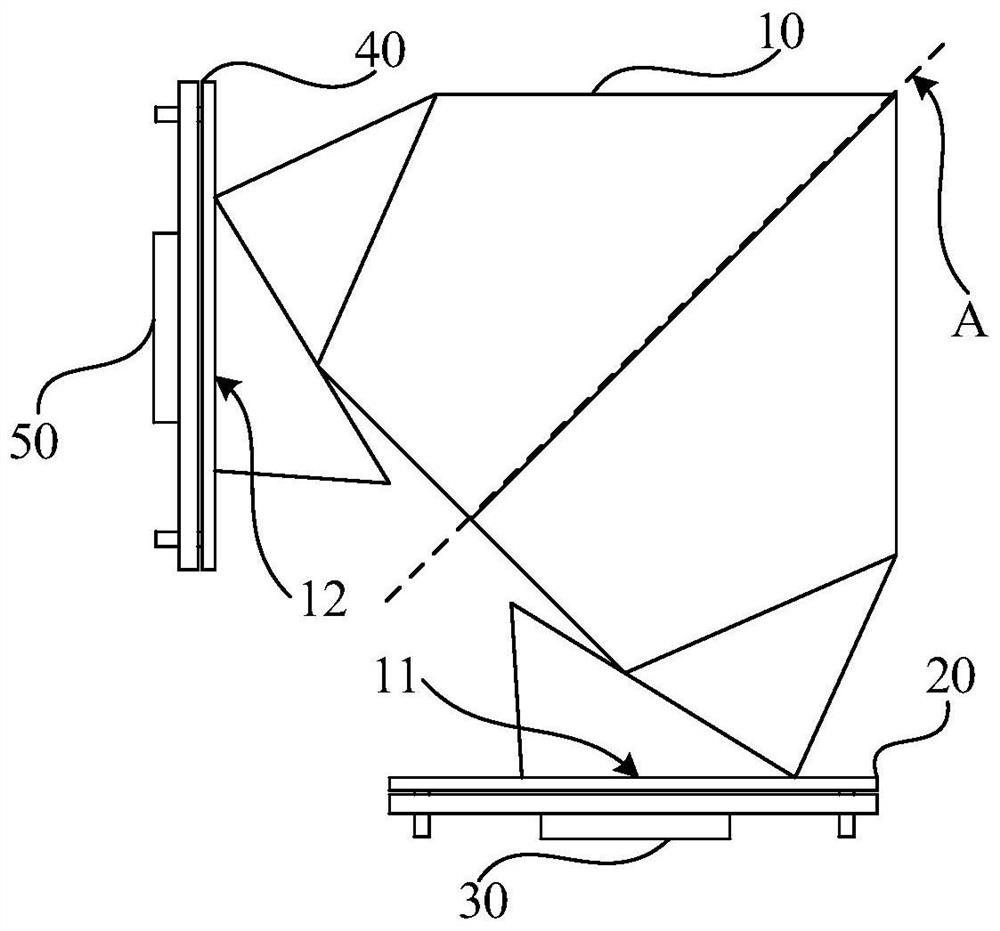
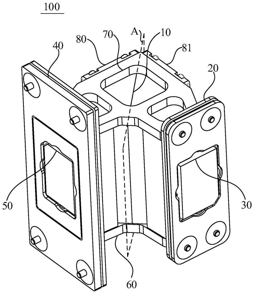
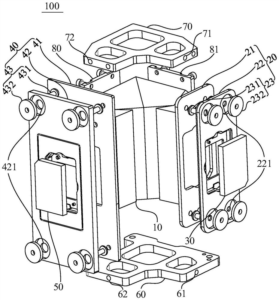
[0023] The following will clearly and completely describe the technical solutions in the embodiments of the application with reference to the drawings in the embodiments of the application. Apparently, the described embodiments are only some of the embodiments of the application, not all of them. Based on the embodiments in this application, all other embodiments obtained by persons of ordinary skill in the art without making creative efforts belong to the scope of protection of this application.

[0024] see figure 1 , figure 2 and image 3 , the embodiment of the present application provides a prism assembly 100, the prism assembly 100 includes: a prism 10, a first fixing mechanism 20, a second fixing mechanism 40, a base 60, a cover plate 70, a first side plate 80 and a second side plate Plate 81.

[0025] read on figure 1 , figure 2 and image 3 , The prism 10 can be made of quartz glass, alkali metal halide crystal or optical glass. The prism 10 can be integrally...


PUM


Abstract

The invention discloses a prism assembly and a projection device, the prism assembly comprises a prism, a first fixing mechanism and a second fixing mechanism, the prism is of a symmetrical structureand comprises a first prism surface and a second prism surface, and the first prism surface and the second prism surface are symmetrical relative to a first section; the first fixing mechanism and thefirst prism surface are correspondingly arranged, and the first fixing mechanism is used for installing a first DMD chip; and the second fixing mechanism is arranged corresponding to the second prismsurface, the second fixing mechanism is used for installing a second DMD chip, and the first DMD chip and the second DMD chip are symmetrical about the first section. By means of the mode, the relative displacement of the first DMD chip and the second DMD chip caused by temperature or external force is equal, the probability that images projected by the two DMD chips are dislocated is reduced, and then the stability of the images projected by the prism assembly in the long-time use process is improved.

Description

technical field [0001] The present application relates to the field of optical technology, in particular to a prism assembly and projection equipment. Background technique [0002] In recent years, liquid crystal display (LCD, Liquid Crystal Display) technology has been limited in some applications, and digital light processing (DLP, Digital Light Processing) technology display systems have been continuously developed. The core of the DLP projection display method is to provide a spatial light modulation unit, and a digital microlens device (DMD, Digital Micromirror Device), as a reflective spatial light modulator, occupies a very important position in the field of projection applications. Compared with projection LCD technology, DLP technology using DMD has more advantages in terms of size and response speed, so it has a good development prospect in the market. [0003] The DMD chip in the existing prism is easily affected by external force or temperature, causing the rela...

Claims


Application Information

Patent Timeline
Patent Type & Authority Applications(China)
IPC IPC(8): G03B21/28G03B21/00
CPCG03B21/008G03B21/28G03B21/00G03B21/14
Inventor 周建华周正平张贤鹏余新李屹
Owner APPOTRONICS CORP LTD
Learn More