
Laser packaging method

A technology of laser encapsulation and laser beam, which is applied in glass forming, glass manufacturing equipment, electrical components, etc., and can solve problems such as missed firing, decreased yield, encapsulation quality, and overburning

Active Publication Date: 2020-12-01
SHANGHAI MICRO ELECTRONICS EQUIP (GRP) CO LTD
View PDF5 Cites 0 Cited by
  • Summary
  • Abstract
  • Description
  • Claims
  • Application Information

AI Technical Summary

Problems solved by technology

However, due to the difference in the structure (or circuit) on the surface of the glass substrate coated with glass frit, when using the same power and scanning rate for encapsulation, a good encapsulation effect can be achieved in some areas, but in another specific area (such as TP lead area of ​​the OLED glass substrate), but there will be missing or over-burning or even cracks, resulting in a decrease in productivity (or packaging quality), so it is necessary to find a laser packaging solution that can take into account both productivity and packaging efficiency

Method used

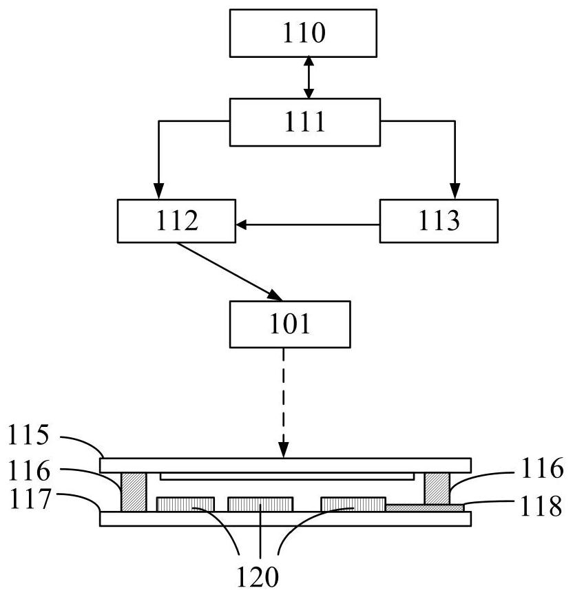
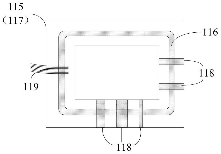

Image

  • Laser packaging method
  • Laser packaging method
  • Laser packaging method

Examples


Embodiment Construction

[0035] As mentioned in the background art, when using a single scan rate and laser power to package a group of glass plates, due to the difference in the surface settings of the glass plates, when the traditional laser packaging method is used to irradiate the glass frit in some specific areas, when the laser power is higher If the scanning rate is too large or the scanning rate is too slow, overburning or even cracks may occur, resulting in a decrease in yield, and it is difficult to improve packaging efficiency.

[0036] In order to improve packaging efficiency and product qualification rate while taking into account the packaging quality, the present invention provides a laser packaging method, which uses laser beams to irradiate glass frit coated along a packaging path between a group of glass substrates for packaging. The packaging path includes a crackable area (the "crackable area" here refers to the area where overburning or cracks are likely to occur when the glass fri...


PUM


Abstract

The invention provides a laser packaging method. A laser beam is used to irradiate frit coated between a group of glass substrates along a packaging path for packaging, the packaging path comprises afragile area, and when the laser beam passes through the fragile area, the laser power is reduced or the laser power and the scanning rate are reduced at the same time. Different laser powers and scanning rates are adopted in the fragile area and other areas of the packaging path. On one hand, the fragile region can be protected from being overburnt and damaged by overhigh laser power, and on theother hand, high laser power and a high scanning rate can be adopted in the region outside the fragile region, so that the packaging efficiency and the product percent of pass are improved, and the yield is increased.

Description

technical field [0001] The invention relates to the field of glass substrate packaging, in particular to a laser packaging method. Background technique [0002] Glass substrates are commonly used in fields such as flat panel displays and solar cells as substrates for making structures such as OLED devices and photovoltaic devices. In order to prevent device degradation, polymer adhesives or high-temperature sintered glass frit are usually used to separate A glass cover plate is bonded to the glass substrate to form a glass sealing body. Similar glass seals are also used in other fields, such as preventing electrolyte leakage in BIPV (Building Integrated Photovoltaic) module manufacturing, preventing discharge gas leakage in PDP panel manufacturing, and double-layer vacuum glass structures that require long-term Maintain a high vacuum and so on. [0003] Compared with the polymer adhesive method, the use of glass frit as the sealing material can achieve better airtightness....

Claims


Application Information

Patent Timeline
IPC IPC(8): H01L51/56C03B23/203
CPCC03B23/203H10K71/00
Inventor 唐江锋李运锋
Owner SHANGHAI MICRO ELECTRONICS EQUIP (GRP) CO LTD
Learn More