
Cleaning tool for cylinder seat of aircraft brake device

The technology of a brake device and a cylinder seat is applied in the direction of using liquid cleaning methods, cleaning methods and utensils, chemical instruments and methods, etc., which can solve the problems of poor cleaning effect and low cleaning efficiency, and achieve improved cleaning efficiency and comprehensive cleaning range , The effect of eliminating pollution sources

Active Publication Date: 2020-12-04
XIAN AVIATION BRAKE TECH
View PDF23 Cites 0 Cited by
  • Summary
  • Abstract
  • Description
  • Claims
  • Application Information

AI Technical Summary

Problems solved by technology

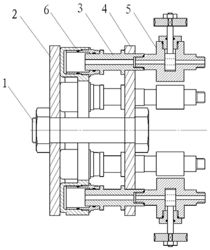
[0004] In order to solve the above-mentioned technical problems, the embodiment of the present invention provides a cylinder block cleaning tool for aircraft brakes to solve the problems of poor cleaning effect and low cleaning efficiency in the existing cleaning methods of aircraft brakes, so as to improve the cleaning effect and Improve cleaning efficiency

Method used


Image

  • Cleaning tool for cylinder seat of aircraft brake device
  • Cleaning tool for cylinder seat of aircraft brake device
  • Cleaning tool for cylinder seat of aircraft brake device

Examples


Embodiment 1

[0057] See attached figure 1 , Figure 6 , with Figure 4 and Figure 5 . The cylinder block cleaning tool for the aircraft braking device provided in this embodiment may include: an adapter 3 , a pressure plate 2 , a fixing plate 4 , a bolt 1 , and a switch 5 . The number of pieces of the adapter 3 and the switch 5 is the same, and is equal to the number of the cleaned aircraft brake device cylinder block piston holes. There is no protrusion on the end face of the cylinder block 6 of the aircraft braking device of this embodiment, and the oil inlet and the air release nozzle are on the side of the cylinder block 6 periphery, and the axes of the oil inlet and the air release nozzle are parallel to the two end faces of the cylinder block 6, and the cylinder block There are 6 evenly distributed piston holes on one side of 6, therefore, there are 6 adapters 3 and 6 switches 5. In this embodiment, the piston hole of the cylinder block is equipped with a piston bushing with a ...

Embodiment 2

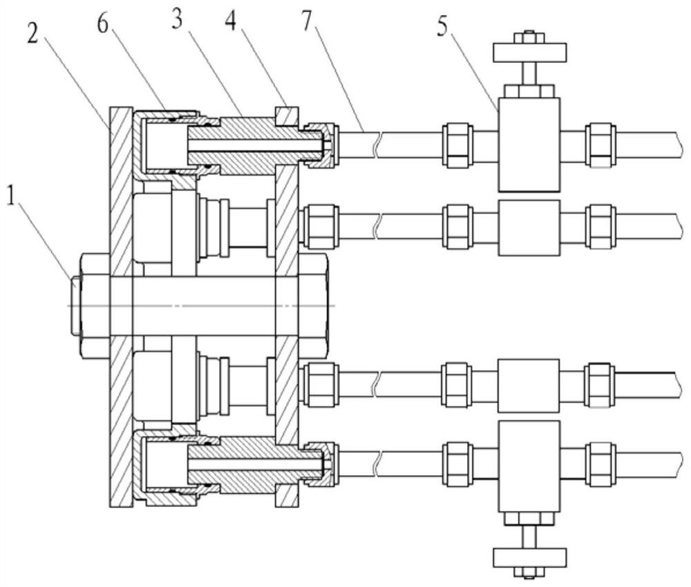
[0069] This embodiment differs from Embodiment 1 in that: 1. The shoulders arranged on the outer diameter near the two ends of the adapter 3 are connected as a whole, and the threaded interface of the oil outlet is an external threaded interface (such as Figure 7 Shown adapter 3); 2. The switch 5 is connected to the threaded joint of the oil outlet of the adapter 3 through the conduit 7 (such as figure 2 3. The oil inlet hydraulic interface of the aircraft brake device is located on the end face of the cylinder block 6, and there is a through hole near the periphery of the pressure plate 2, or a gap or a notch on the periphery to accommodate the connection of the oil inlet nozzle (such as Figure 8 to Figure 10 Platen 2) shown.

[0070] see figure 2 , Figure 4 , Figure 7 to Figure 11 . The cylinder block cleaning tool for the aircraft braking device provided in this embodiment may include: an adapter 3, a pressure plate 2, a fixing plate 4, a bolt 1, a switch 5, and t...

Embodiment 3

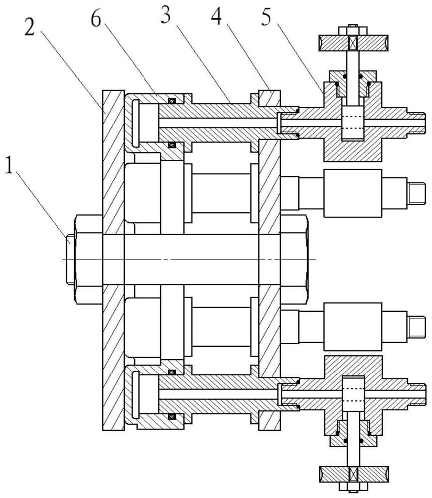
[0082] see Figure 3 to Figure 4 , Figure 6 , Figure 8 to Figure 11 . The difference between this embodiment and Embodiment 1 is that the cleaned aircraft brake device cylinder block 6 piston hole does not have a piston bushing, and the piston is directly installed in the cylinder block 6 piston hole. There are protrusions on the end surface of the cylinder block 6 of the aircraft brake device, and the oil inlet 8 is located on the end surface of the cylinder block 6, and the number is 2. For this reason, a through hole is opened near the periphery of the pressure plate 2, or a gap or a notch is opened on the periphery of the pressure plate 2. To accommodate the screw plug connected to the oil inlet nozzle and to avoid blocking the other oil inlet.

[0083] The cylinder block cleaning tool for the aircraft braking device provided in this embodiment may include: an adapter 3, a pressure plate 2, a fixing plate 4, a bolt 1, a switch 5, and the like. The number of pieces of...


PUM


Abstract

An embodiment of the invention discloses a cleaning tool for a cylinder seat of an aircraft brake device. The cleaning tool comprises adapters, a pressing plate, a fixed plate, a bolt and switches, wherein the pressing plate is arranged at the bottom of the cylinder seat; the adapters are arranged in piston holes of the cylinder seat, a cavity is arranged between each adapter and the correspondingpiston hole, and the inner cavity of each piston hole communicates into a cleaning oil return pipeline; through holes in one-to-one correspondence with the adapters are distributed in the circumferential direction of the fixed plate, one end of each adapter is inserted into the corresponding piston hole in the cylinder seat while the other end of each adapter is arranged in the corresponding through hole in the fixed plate and extends out, and one end, extending out of the fixed plate, of each adapter is connected to the corresponding switch or connected to the corresponding switch through aguide pipe; and the bolt penetrates into a bolt hole in the center of the fixed plate, passes through the center of the cylinder seat and penetrates through the bolt hole in the center of the pressingplate in order to extend out of the end face of the pressing plate, and the fixed plate, the adapters, the cylinder seat and the pressing plate are assembled and fixed together through the bolt and nuts. According to the embodiment of the invention, the problems of poor cleaning effect and low cleaning efficiency of an existing cleaning method for the aircraft brake device are solved.

Description

technical field [0001] The present application relates to but not limited to the technical field of cleaning the inner cavity of the aircraft wheel brake device, especially a cylinder block cleaning tool for the aircraft brake device. Background technique [0002] The disc brake device is a kind of aircraft wheel brake device widely used in the current aircraft, and the cylinder block is one of the main components of this type of brake device. Since the aircraft wheel brake device is a dead space in the hydraulic system, the hydraulic oil does not form a closed-loop return oil circuit, and the surface processing residues such as aluminum chips and oil in the inner cavity of the cylinder block (the cavity formed by the piston hole and the communication channel of the piston hole) Dirt in the liquid is very harmful to the aircraft brake system using electro-hydraulic servo valves. It has been recognized from the use practice that the aircraft brake device needs to be included ...

Claims


Application Information

Patent Timeline
Patent Type & Authority Applications(China)
IPC IPC(8): B08B3/02B08B13/00
CPCB08B3/02B08B13/00
Inventor 何永乐赵文庆马建峰
Owner XIAN AVIATION BRAKE TECH
Learn More