Building waste treatment device for civil engineering

A construction waste and processing device technology, applied in construction waste recycling, grain processing, solid waste removal, etc., can solve the problems of inconvenient recycling work, inconvenient waste reuse requirements, and inconvenient recycling work due to the degree of broken metal parts. achieve the effect of separation

Pending Publication Date: 2020-12-04
刘凤翔
View PDF12 Cites 7 Cited by
  • Summary
  • Abstract
  • Description
  • Claims
  • Application Information

AI Technical Summary

Problems solved by technology

[0003] In the process of processing construction waste in the existing civil engineering construction waste, crushing rollers are often used to crush the metal parts directly, and then the metal parts in the crushed waste are screened. This method is likely to cause the metal parts in the crushing process to be broken It is not convenient for recycling, and during the recycling process, the metal parts pressed at the bottom of the waste particles are not convenient for recycling, and the waste particles in the processing process are one-time molded products, which is not convenient for meeting different waste recycling needs

Method used


Image

  • Building waste treatment device for civil engineering
  • Building waste treatment device for civil engineering
  • Building waste treatment device for civil engineering

Examples


Embodiment Construction

[0029] In order to make the purpose, technical solutions and advantages of the embodiments of the present invention clearer, the technical solutions in the embodiments of the present invention will be clearly and completely described below in conjunction with the drawings in the embodiments of the present invention. Obviously, the described embodiments It is a part of embodiments of the present invention, but not all embodiments. Based on the embodiments of the present invention, all other embodiments obtained by persons of ordinary skill in the art without creative efforts fall within the protection scope of the present invention.

[0030] In describing the present invention, it should be understood that the terms "center", "longitudinal", "transverse", "upper", "lower", "front", "rear", "left", "right", " The orientations or positional relationships indicated by "vertical", "horizontal", "top", "bottom", "inner", "outer", "axial", "radial", and "circumferential" are based on t...


PUM


Abstract

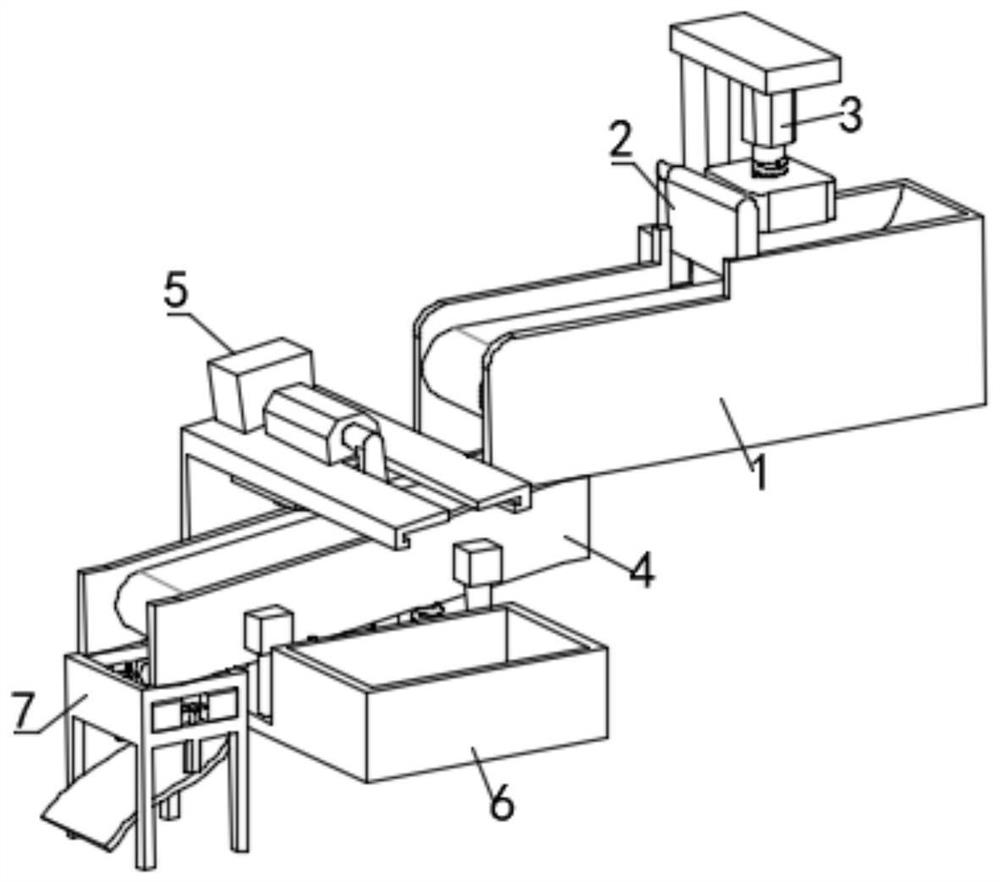
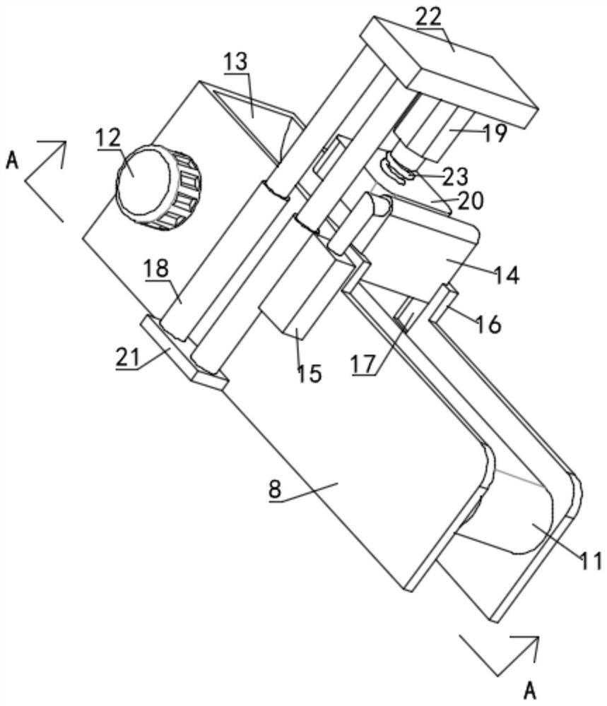
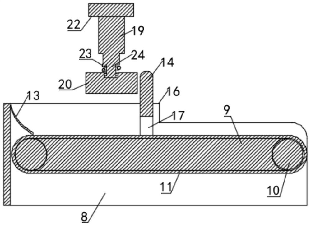
The embodiment of the invention discloses a building waste treatment device for civil engineering in the technical field of civil engineering. The building waste treatment device comprises a first conveying mechanism, a height limiting adjusting mechanism, an air hammer knocking mechanism and a second conveying mechanism; the first conveying mechanism is transversely arranged, the height limitingadjusting mechanism is used for filtering waste particles on the first conveying mechanism, the air hammer knocking mechanism is used for conducting waste crushing on the conveying starting end of thefirst conveying mechanism, and the second conveying mechanism is obliquely arranged on one side of the bottom of the conveying tail end of the first conveying mechanism for shaking and conveying waste materials. According to the building waste treatment device for civil engineering, through the three procedures of waste knocking treatment, metal part separation treatment and crushing treatment, the waste particles with different particle sizes can be fully knocked and crushed, so that the metal parts and the waste particles are thoroughly separated, and the metal parts and the waste particlesare conveyed through shaking, an electromagnet is used for better completing the recovery work of the metal parts, and meanwhile, the particle size requirements of the waste particles with differentrequirements can be met by adjusting crushing treatment.

Description

technical field [0001] The embodiments of the present invention relate to the technical field of civil engineering, in particular to a device for processing construction waste in civil engineering. Background technique [0002] With the acceleration of urbanization, urban reconstruction and the rapid development of the construction industry, more and more urban infrastructures are being built. In the process of constructing subways, roads and urban buildings, it is necessary to destroy the original pavement and During the construction of the foundation pit, a large amount of earthwork construction waste will be generated, the most of which is dregs. If the muck is not treated and utilized in time, it will definitely have adverse effects on society, the environment and resources. During construction operations, the common way to dispose of the muck is to transport it by means of a muck truck. This method is costly, and the muck transported outside still cannot be treated in a...

Claims


Application Information

Patent Timeline
Patent Type & Authority Applications(China)
IPC IPC(8): B09B3/00B09B5/00B02C4/02B02C4/32B03C1/005B03C1/22F16F15/067
CPCB09B3/00B09B5/00B02C4/02B02C4/32B03C1/005B03C1/22F16F15/067B02C2201/06Y02W30/58
Inventor 刘凤翔
Owner 刘凤翔
Why Eureka
Try Eureka