
Mechanical arm autonomous calibration method based on visual measurement

A calibration method and visual measurement technology, applied to manipulators, program-controlled manipulators, manufacturing tools, etc.

Active Publication Date: 2020-12-04
SHENYANG JIANZHU UNIVERSITY
View PDF6 Cites 7 Cited by
  • Summary
  • Abstract
  • Description
  • Claims
  • Application Information

AI Technical Summary

Problems solved by technology

[0004] The purpose of the present invention is to provide a method for autonomous calibration of a robotic arm based on visual measurement, which solves the problem of a certain temperature difference in the movement of the robotic arm to be calibrated in the prior art

Method used


Image

  • Mechanical arm autonomous calibration method based on visual measurement
  • Mechanical arm autonomous calibration method based on visual measurement
  • Mechanical arm autonomous calibration method based on visual measurement

Examples


Embodiment 1

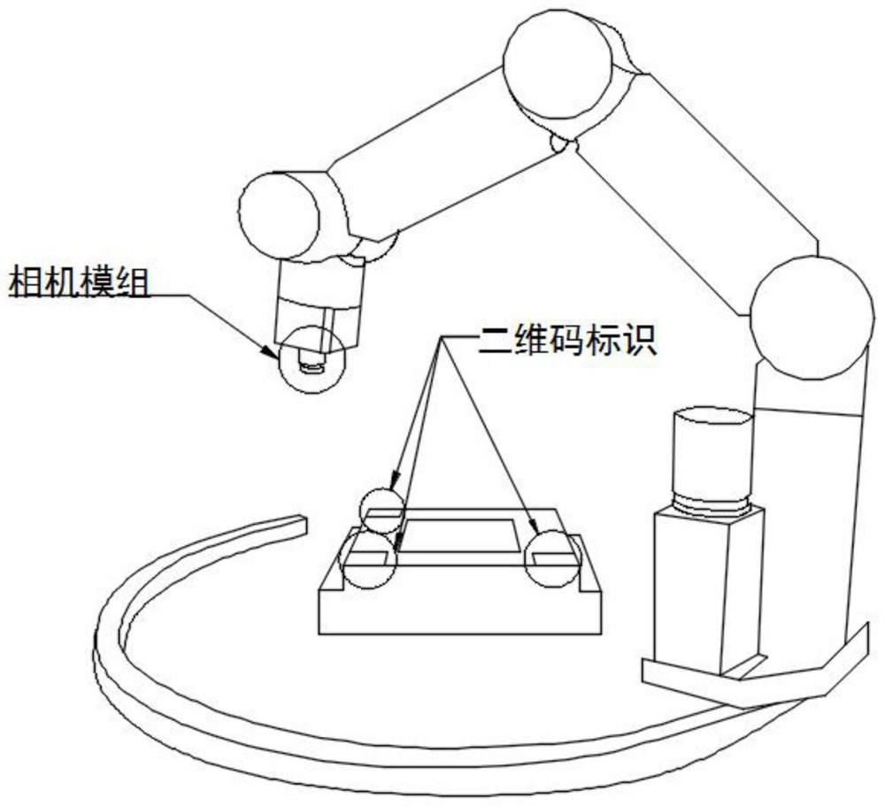
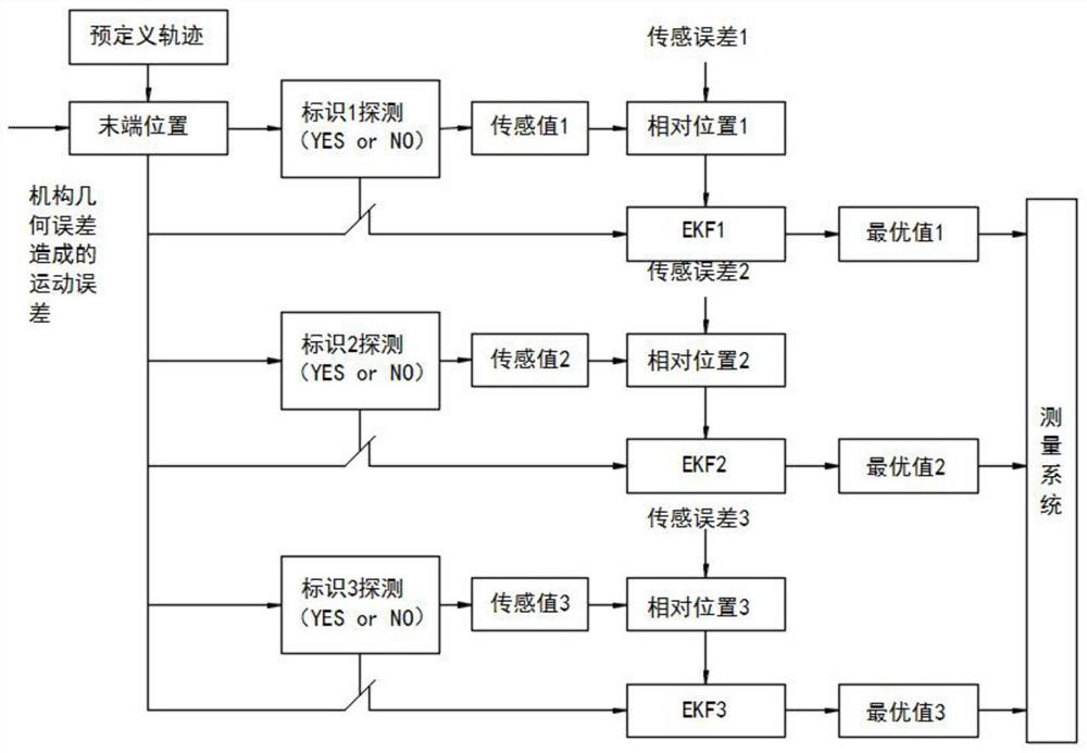
[0112] refer to Figure 1-8 , an autonomous calibration method for manipulators based on visual measurement, including the following steps:

[0113] Step 1: Build an unsteady multi-sensor manipulator vision system;

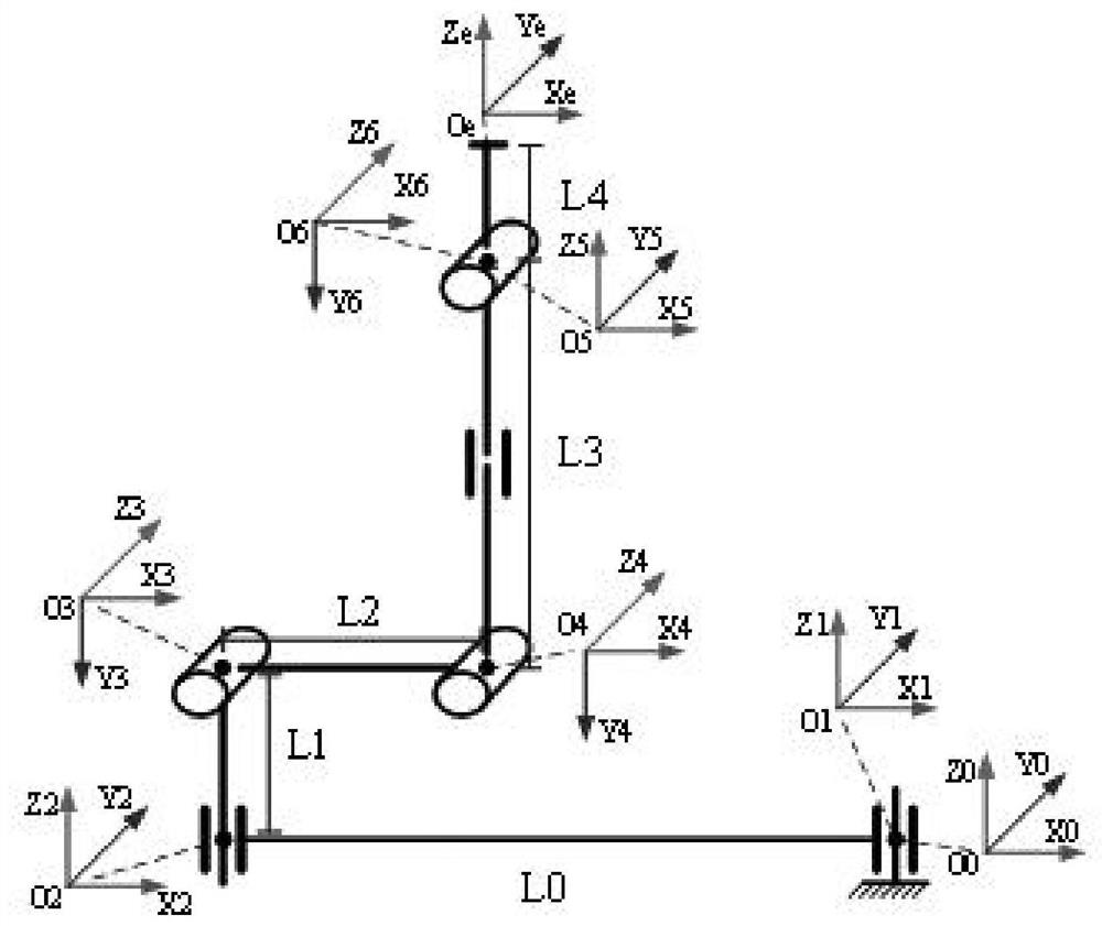
[0114] Taking the life science glove box robotic arm of China Space Station as the research platform, in order to obtain higher positioning accuracy and improve the fit between the model and the actual geometric configuration of the robotic arm, a more stringent improved DH model was established, and a Group of angles, to represent the error angle of the connecting rod rotating around the y-axis, preferably, all angle values ​​are zero; axis 1 is an arc guideway, in the mechanical model, it is abstracted as a rotation axis with a virtual link, the The length of the connecting rod is equal to the radius of the arc guide rail. During the preparation process, the positions of the three two-dimensional code marking points in the base coordinate system are respectivel...


PUM


Abstract

The invention discloses a mechanical arm autonomous calibration method based on vision measurement. The method comprises the following steps that step 1, an unsteady-state multi-sensor mechanical armvision system is constructed; step 2, a calibration model is established according to a Gaussian motion method; step 3, multiple identification points are measured according to extended Kalman filtering; step 4, a motion trail is corrected according to a linear quadratic form regulator; step 5, an optimal measurement point is screened based on a Monte Carlo method; and step 6, model parameters areapproximated by adopting a DH augmentation model. According to the method, through an EKF algorithm filtering process, an LQR method correction process and a calibration data preferred screening process based on error distribution, the optimal calibration precision can be obtained under the condition that mechanical arm motion errors and measurement errors exist at the same time; and moreover, the method is low in cost, high in efficiency and relatively convenient, and can be widely applied to long-term and frequent calibration and maintenance of mechanical arm equipment.

Description

technical field [0001] The invention relates to an autonomous calibration method of a mechanical arm based on vision measurement. Background technique [0002] The calibration of robot positioning accuracy has always been the focus of attention in the industry. Existing research shows that 90% of positioning errors come from the geometric model error of the mechanism. The mechanical structure of the robot is affected by system vibration, overload, collision and wear, and the positioning error will continue to increase. The positioning accuracy of the manipulator can be improved by applying precision measurement tools such as laser trackers and offline calibration algorithms. However, in special environments such as aerospace, nuclear industry, and deep sea, the improvement of the positioning accuracy of unmanned autonomous manipulators is still a technical problem that still plagues the industry, mainly due to two reasons. First of all, there is bound to be a certain error...

Claims


Application Information

Patent Timeline
IPC IPC(8): B25J19/04B25J9/16
CPCB25J9/16B25J9/1664B25J9/1692B25J19/04
Inventor 祁若龙张珂邵健铎毛新元邢运隆
Owner SHENYANG JIANZHU UNIVERSITY
Learn More