
Telephone receiver line rolling rod feeding transfer device and method thereof

A technology for telephone receivers and transfer devices, which can be applied to other household appliances, metal processing, household components, etc., and can solve the problems of poor feed transfer efficiency of rolling rods, etc., to improve order, stability, and connectivity Effect

Inactive Publication Date: 2020-12-04
孙广静
View PDF0 Cites 0 Cited by
  • Summary
  • Abstract
  • Description
  • Claims
  • Application Information

AI Technical Summary

Problems solved by technology

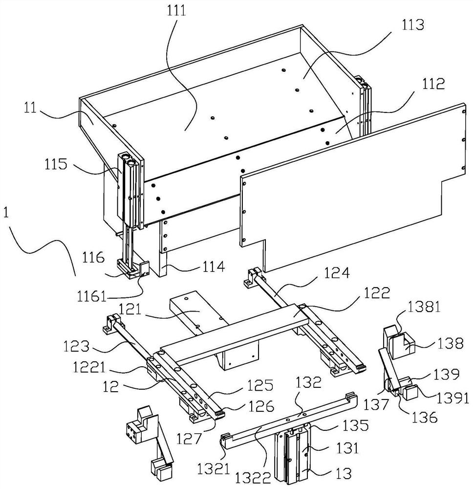
[0007] The object of the present invention is to solve the problem of poor feed transfer efficiency of the existing telephone receiver wire coiling rods, and provide a telephone receiver cord coiling rod feeding transfer device, which facilitates wire-to-wire feeding and transfer through the coiling rod drop channel. The material is discharged to improve the orderliness of feeding; the width of the longitudinal rod passing through the channel limit block matches the width of a rolling rod, and the longitudinal rod on the channel limit block is convenient for better connection with the coiling rod. Cohesion, and at the same time, a good limit is also carried out, so that the rolling rods can be conveyed one by one; the forward and backward transfer blocks of the rolling rods facilitate better connection with the falling channel of the rolling rods, and improve the connection during the feeding transfer process performance, and make the front and rear transfer blocks of the rolling rod better match the two ends of the rolling rod

Method used


Image

  • Telephone receiver line rolling rod feeding transfer device and method thereof
  • Telephone receiver line rolling rod feeding transfer device and method thereof
  • Telephone receiver line rolling rod feeding transfer device and method thereof

Examples


Embodiment Construction

[0032] The specific implementation manner of the present invention will be described in detail below in conjunction with the accompanying drawings.

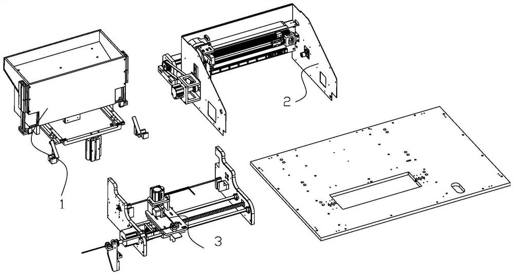
[0033] Such as figure 1 Shown, a kind of telephone handset wire automatic rolling equipment, comprises frame and the rolling bar feeding transfer device 1 on it, rolling bar clamping and rotating device 2 and telephone handset line feeding clamping and cutting device 3; The rolling rod feeding transfer device 1 is located at the rear side of the rolling rod clamping and rotating device 2, and the rolling rod feeding and transferring device 1 is used to feed the rolling rod to the rolling rod clamping and rotating device 2, The rolling rod clamping and rotating device 2 is used to clamp the two ends of the rolling rod and drive the rolling rod to rotate when rolling; the telephone handset wire feeding clamping and cutting device 3 includes a telephone handset wire feeding assembly 31, Telephone handset wire clamping assembly 32 a...


PUM


Abstract

The invention belongs to the technical field of telephone receiver line automatic production, in particular to a telephone receiver line rolling rod feeding transfer device and a method thereof. The telephone receiver line rolling rod feeding transfer device comprises a rolling rod feeding frame, a rolling rod front-back transfer assembly and a rolling rod lifting transfer assembly, wherein a rolling rod cavity used for accommodating a rolling rod is formed in the rolling rod feeding frame; a first downward-sliding slope and a second downward-sliding slope are formed on the front side and therear side of the bottom face of the rolling rod cavity respectively; rolling rod falling channels are formed at the bottom of the first downward-sliding slope on the rolling rod feeding frame; fallingchannel limiting cylinders are arranged on the left side and the right side of the rolling rod feeding frame respectively; a channel limiting block is arranged at the bottom of each falling channel limiting cylinder; and the rolling rod front-back transfer assembly is arranged on a frame and used for driving the rolling rod to be transferred to the rolling rod lifting transfer assembly. Telephonereceiver line rolling rod feeding transfer device and the method thereof have the advantage that the feeding stability and the transfer accuracy of the rolling rod are improved.

Description

technical field [0001] The invention belongs to the technical field of automatic production of telephone handset cords, and in particular relates to a material transfer device and method for a rolling rod of a telephone handset cord. Background technique [0002] The telephone handset line is used to connect the telephone and the handset. The telephone handset line is spiral, and the spiral telephone handset line is convenient to realize expansion and contraction when the telephone is in use, and it is convenient to lengthen the distance between the microphone and the telephone when making a call , At the end of the call, it is convenient to shrink the telephone receiver line, reduce the occupied area, and also facilitate the storage of the telephone receiver line. [0003] The rolling rod, telephone handset wire and splint are needed in the production process of the telephone handset wire rolling; the telephone handset wire is fixed at one end of the telephone handset wire ...

Claims


Application Information

Patent Timeline
IPC IPC(8): B29C53/12B29C53/80B29C31/00B26D1/06B29L31/34
CPCB26D1/06B29C31/008B29C53/12B29C53/80B29L2031/3431
Inventor 孙广静徐盼盼徐平丽
Owner 孙广静
Learn More