Method for reading data with storage system, data managing system for storage system and storage system

a technology for managing systems and data, applied in the direction of micro-instruction address formation, memory address/allocation/relocation, instruments, etc., to achieve the effect of shortening and stabilizing the time necessary

Inactive Publication Date: 2009-05-14
HITACHI LTD
View PDF0 Cites 29 Cited by
  • Summary
  • Abstract
  • Description
  • Claims
  • Application Information

AI Technical Summary

Benefits of technology

[0008]It is therefore an object of this invention to provide a data reading method that arranges read requests in an optimum order for each physical disk drive despite a change in data location caused by dynamic data migration within a storage system from the use of the storage system's virtualization functions and OS′ virtualization functions.
[0010]This invention can thus issue data read requests in an optimum order based on data placement that reflects a dynamic change in physical location of data in a storage system, thereby making it possible to shorten and stabilize the time necessary to make a data inquiry to the storage system.

Problems solved by technology

In short, there arise problems in that reallocating queued read requests does not shorten the head seek time or rotational latency of physical disk drives if there is a change in data location after the AP or the OS recognizes the placement of data.

Method used


Image

  • Method for reading data with storage system, data managing system for storage system and storage system
  • Method for reading data with storage system, data managing system for storage system and storage system
  • Method for reading data with storage system, data managing system for storage system and storage system

Examples


first embodiment

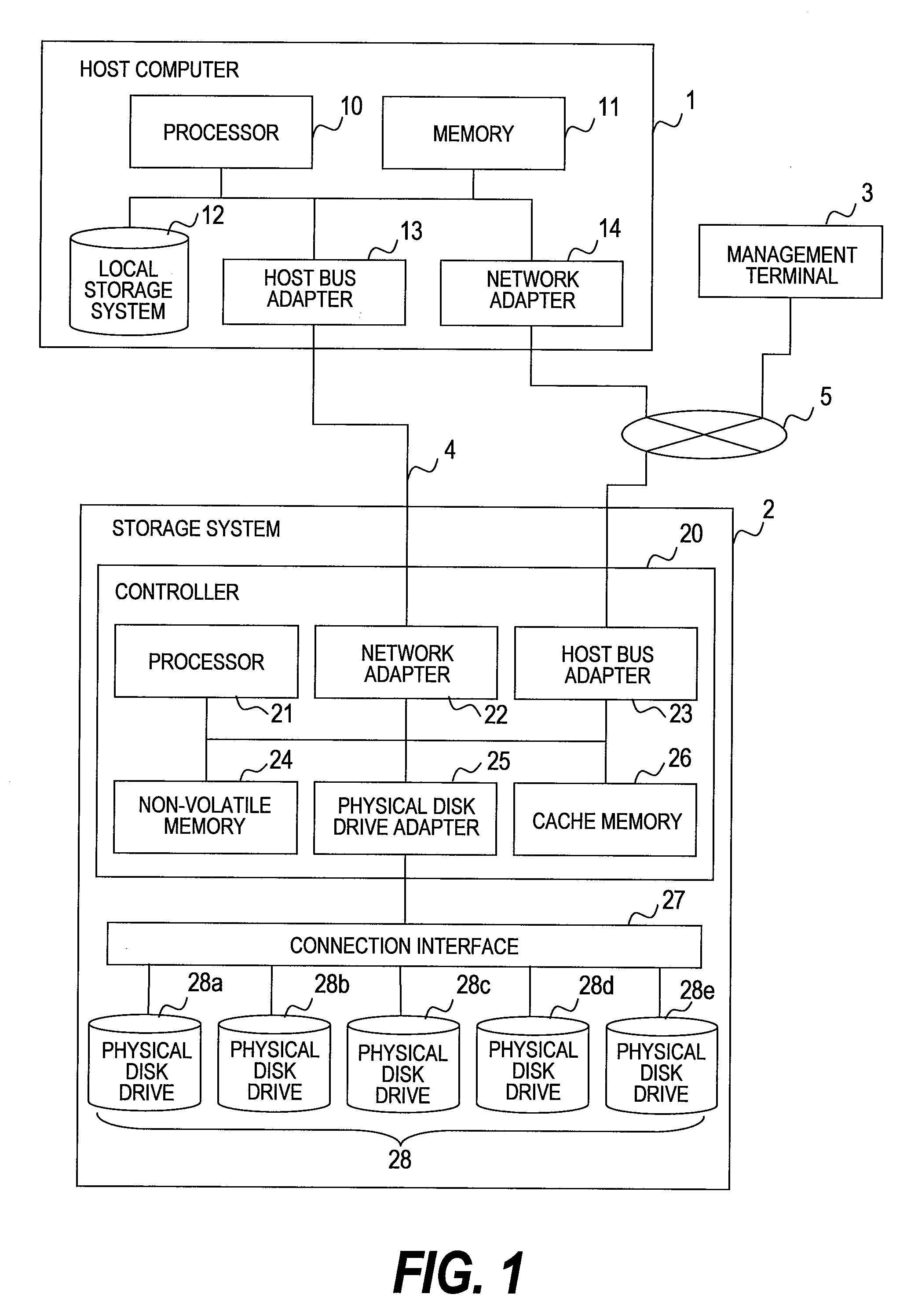
[0029]FIG. 1 is a block diagram showing the hardware configuration of an information processing system (computer system) according to a first embodiment of this invention.

[0030]The information processing system of FIG. 1 has a host computer 1, a storage system 2, a management terminal 3, a network 4, and a network 5.

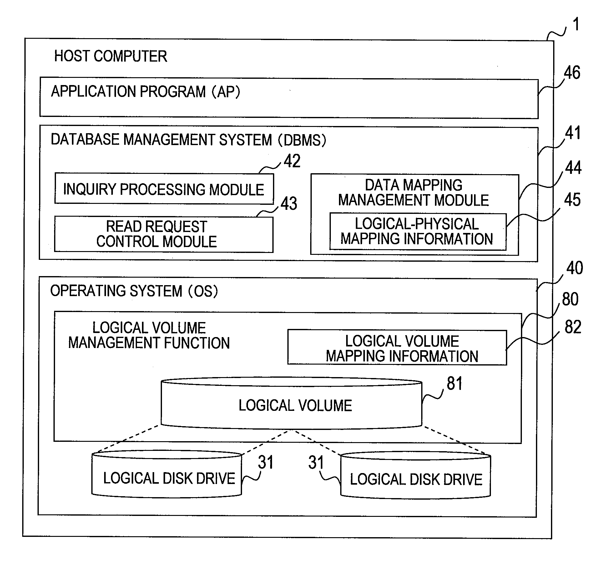
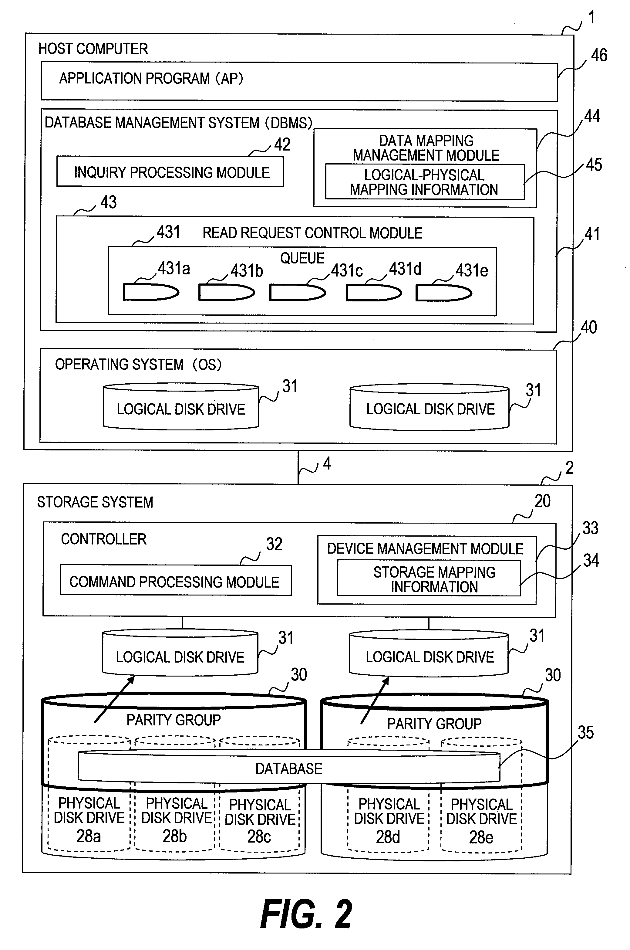
[0031]The host computer 1 is a computer such as a personal computer, a workstation, or a mainframe. The host computer 1 runs an operating system (OS) fit to the type of the computer, a database management system (DBMS) for accumulating and managing business operation data, and an application program (AP) for issuing inquiries to the DBMS. The OS, the DBMS, and the AP will be described later with reference to FIG. 2.

[0032]The host computer 1 has a processor 10, a memory 11, local storage system 12, a host bus adapter 13, and a network adapter 14.

[0033]The processor 10 executes the OS, the DBMS, the AP, and other programs. The memory 11 temporarily stores the programs exec...

second embodiment

[0154]A second embodiment of this invention will be described below. The description will focus on the differences from the first embodiment of this invention, and components that provide the same functions as the components in the first embodiment of this invention will be denoted by the same reference symbols in order to omit repetitive descriptions.

[0155]The first embodiment describes a mode of applying this invention to an information processing system that allows dynamic data migration within the storage system 2. The second embodiment describes a mode of applying this invention to an information processing system that allows dynamic data migration within the OS 40 of the host computer 1 in addition to one within the storage system 2.

[0156]FIG. 13 is a diagram showing the logical configuration of the host computer 1 according to the second embodiment of this invention. The hardware configuration of the information processing system and the logical configuration of the storage s...

third embodiment

[0199]A third embodiment of this invention will be described below. The description will focus on the differences from the first and second embodiments, and components that provide the same functions as the components in the first and second embodiments will be denoted by the same reference symbols in order to omit repetitive descriptions.

[0200]The first embodiment shows an example in which the DBMS 41 obtains the storage mapping information 34 from the storage system 2 and reallocates read requests by physical addresses in the physical disk drives 28. The second embodiment shows an example in which the logical volume mapping information 82 is obtained from the logical volume management function 80 within the host computer 1 and read requests are reallocated by physical addresses in the physical disk drives 28. Described in the third embodiment is a mode in which the management terminal 3 keeps the storage mapping information 34 and logical volume management information and the DBMS...


PUM


Abstract

Provided is a database management system obtains storage mapping information which associates addresses in a plurality of physical disk drives within the storage system and addresses in logical disk drives including these physical disk drives, to create queues individually for each of the plurality of physical disk drives. The database management system receives a plurality of read requests which request to read data out of the physical disk drives via the logical disk drives provided by the storage system, sorts the read requests by their destination, and accumulates the read requests in the respective queues associated with the request destination physical disk drives. The database management system reallocates the accumulated read requests into an order that shortens the data read time in each physical disk drive, and then issues the read requests to the storage system.

Description

CLAIM OF PRIORITY[0001]The present application claims priority from Japanese application P2007-291936 filed on Nov. 9, 2007, the content of which is hereby incorporated by reference into this application.BACKGROUND OF THE INVENTION[0002]This invention relates to a technique that enables a computer to read data stored in a storage system.[0003]In corporate activities, handling and utilizing a huge amount of business operation data has become essential. Therefore, the systems that multi-dimensionally analyze business operation data accumulated in massive amount in a database (hereinafter, referred to as “DB”) have widely been diffused. In this analysis processing, a database management system (hereinafter, referred to as “DBMS”) receives an inquiry and issues multiple data read requests to a storage system that stores the DB.[0004]One of conventional technologies for executing multiple-data read processing efficiently is I / O scheduling. In I / O scheduling, a DBMS or similar application...

Claims


Application Information

Patent Timeline
Patent Type & Authority Applications(United States)
IPC IPC(8): G06F12/02
CPCG06F3/0611G06F3/067G06F3/0656G06F3/0647
Inventor TOKUDA, SEISUKESHIMIZU, AKIRA
Owner HITACHI LTD
Why Eureka
Try Eureka