High-load-bearing transfer trolley for lithium battery processing and production

A lithium battery and transfer vehicle technology, which is applied in the direction of trolleys, motor vehicles, multi-axis trolleys, etc., can solve the problems of inability to adjust the transport volume of transfer vehicles, insufficient carrying capacity, inconvenient loading and unloading, etc., and achieve good shock absorption and buffering functions , increase the use area, convenient loading and unloading effect

Inactive Publication Date: 2020-12-04
周越
View PDF0 Cites 2 Cited by
  • Summary
  • Abstract
  • Description
  • Claims
  • Application Information

AI Technical Summary

Problems solved by technology

[0003] In the process of lithium battery processing and production, it is necessary to transfer the bagged lithium battery raw materials at different positions. The existing bagged lithium battery raw material transportation transfer vehicle has a weak load-bearing capacity, and long-term use will cause the surface of the transfer vehicle to be submerged. Concave, so that the carrying capacity is not enough each time, and the height of the guard bar cannot be adjusted according to the transport volume of the bagged lithium battery raw materials each time, resulting in the bagged lithium battery raw materials that exceed the height of the guard bar easily slipping off. Or when loading and unloading, it is inconvenient to load and unload due to the height of the guardrail, and it is laborious. At the same time, in the case of a large amount of transportation, the transportation volume of the transfer vehicle cannot be adjusted each time, and the efficiency is low and cannot meet the needs of use. Design a high load-bearing transfer vehicle for lithium battery processing and production to solve the above problems

Method used


Image

  • High-load-bearing transfer trolley for lithium battery processing and production
  • High-load-bearing transfer trolley for lithium battery processing and production
  • High-load-bearing transfer trolley for lithium battery processing and production

Examples


Embodiment Construction

[0025] The following will clearly and completely describe the technical solutions in the embodiments of the present invention with reference to the accompanying drawings in the embodiments of the present invention. Obviously, the described embodiments are only some, not all, embodiments of the present invention. Based on the embodiments of the present invention, all other embodiments obtained by persons of ordinary skill in the art without making creative efforts belong to the protection scope of the present invention.

[0026] It should be noted that when a component is said to be "fixed" to another component, it can be directly on the other component or there can also be an intervening component. When a component is said to be "connected" to another component, it may be directly connected to the other component or there may be intervening components at the same time. When a component is said to be "set on" another component, it may be set directly on the other component or t...


PUM


Abstract

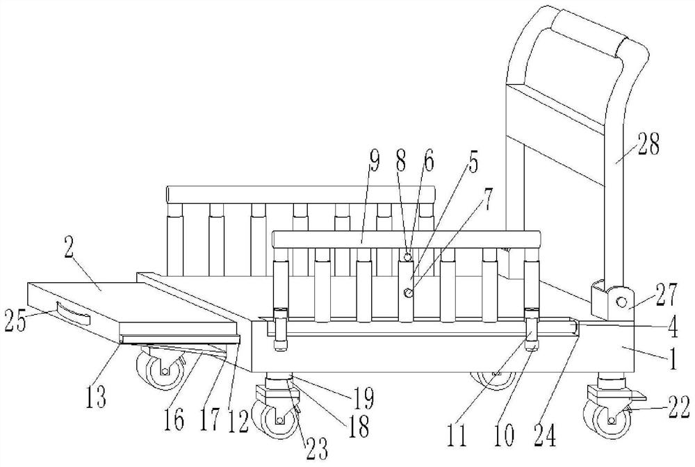
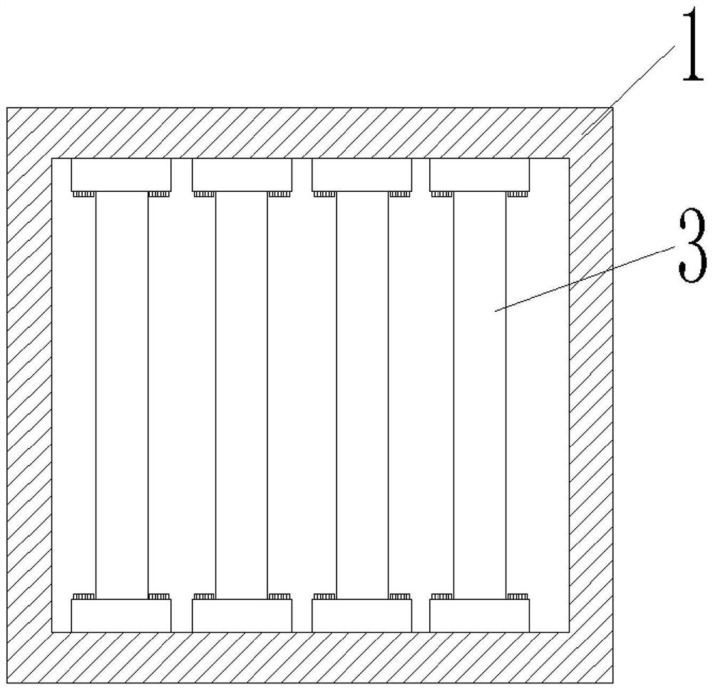
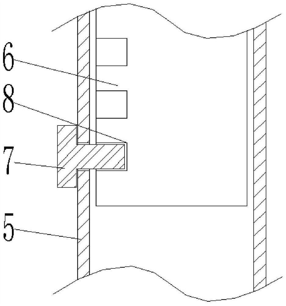
The invention discloses a high-load-bearing transfer trolley for lithium battery processing and production. The trolley comprises a bearing plate and a sliding plate, load-bearing square rods are installed on the inner walls of the two sides of the bearing plate and the inner wall of the two sides of the sliding plate through bolts, rotating grooves are formed in the outer walls of the two sides of the top of the bearing plate, and rotating rods are rotatably connected to the inner walls of the two ends of each rotating groove through bearings; first protection rods distributed at equal intervals are welded to the outer wall of the top of each rotating rod, second protection rods are inserted into the top ends of the first protection rods, and fixing bolts are in threaded connection with the outer walls of the front faces of the two first protection rods. According to the transfer trolley, the load-bearing square rods are mounted in the bearing plate and the sliding plate, so that thetransfer trolley can bear larger load, the surface of the transfer trolley is prevented from sinking downwards after long-time use, the toughness of the transfer trolley is improved, the heights of the second protection rods can be adjusted, and bagged lithium battery raw materials exceeding the height part of the protection rods are prevented from sliding off from the transfer trolley; and meanwhile, the vertical use area of the transfer trolley is increased.

Description

technical field [0001] The invention relates to the technical field of lithium battery processing, in particular to a high-load-bearing transfer vehicle for lithium battery processing and production. Background technique [0002] A lithium battery is a battery that uses lithium metal or lithium alloy as the anode material and uses a non-aqueous electrolyte solution. The difference between lithium battery and lithium ion battery is that the former is a primary battery and the latter is a rechargeable battery. Due to the very active chemical properties of lithium metal, the processing, storage and use of lithium metal have very high environmental requirements, so lithium batteries have not been used for a long time. With the development of microelectronics technology at the end of the 20th century, miniaturized equipment is increasing day by day, which puts forward high requirements on power supply, and lithium batteries have entered a large-scale practical stage. [0003] I...

Claims


Application Information

Patent Timeline
IPC IPC(8): B62B3/02B62B5/00
CPCB62B3/02B62B5/0006B62B2202/61
Inventor 周越
Owner 周越
Why Eureka
Try Eureka