A dual-motor drive system for oil drilling and its control method

A dual-motor-driven, oil drilling technology, applied in the automatic control system of drilling, drilling equipment and methods, drilling equipment, etc., can solve the problems of large loss, high cost, low reliability, etc., and achieve large loss and high cost. , the effect of low reliability

Active Publication Date: 2021-08-24
江苏辰午节能科技股份有限公司
View PDF24 Cites 0 Cited by
  • Summary
  • Abstract
  • Description
  • Claims
  • Application Information

AI Technical Summary

Problems solved by technology

[0002] Existing diesel engines or diesel generators that provide power for drilling production consume a large amount of diesel oil and cause pollution to the surrounding environment. Major oil fields gradually use the grid to supply power to AC variable frequency motors within the coverage of the power grid, and provide power for drilling through AC variable frequency motors
For the power required for drilling due to the wide distribution of drilling conditions, direct use of a single motor drive has high costs, large losses, low reliability, and is not economical. Two motors of the same type are used. When the drilling power demand is small, a single motor is used. operation; when the demand is large, two motors are used to run in parallel
When two motors are running in parallel, if the torque of the two motors is inconsistent, the motors will drag each other, and the motor with a higher speed will drive the motor with a lower speed to rotate, which will cause the motor to enter the power generation state and cause the inverter to fail. , but there are few researches on the design and control of oil drilling dual motor drive system

Method used


Image

  • A dual-motor drive system for oil drilling and its control method
  • A dual-motor drive system for oil drilling and its control method
  • A dual-motor drive system for oil drilling and its control method

Examples


Embodiment Construction

[0036] It should be noted that, in the case of no conflict, the embodiments in the present application and the features in the embodiments can be combined with each other. The present invention will be described in detail below with reference to the accompanying drawings and examples.

[0037] It should be noted that the terminology used here is only for describing specific implementations, and is not intended to limit the exemplary implementations according to the present application. As used herein, unless the context clearly dictates otherwise, the singular is intended to include the plural, and it should also be understood that when the terms "comprising" and / or "comprising" are used in this specification, they mean There are features, steps, operations, means, components and / or combinations thereof.

[0038]It should be noted that the terms "first" and "second" in the specification, claims and drawings of the present application are used to distinguish similar objects, b...


PUM


Abstract

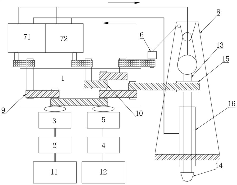
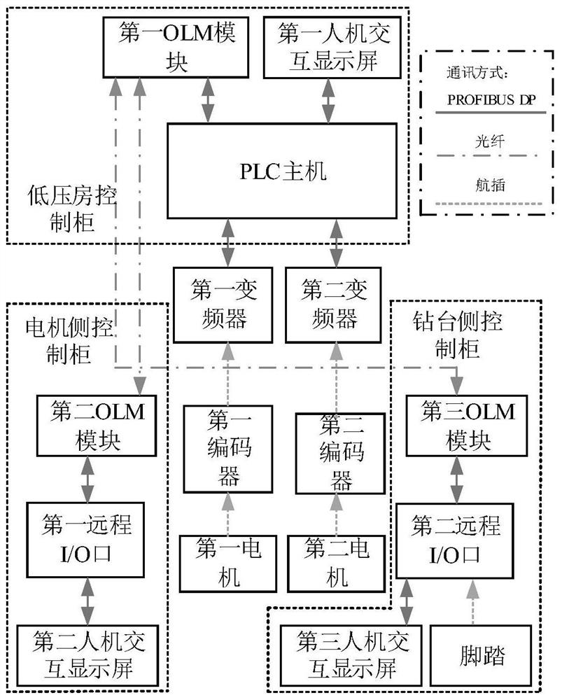
The invention discloses a dual-motor drive system for oil drilling and a control method thereof. The dual-motor cooperative operation control for driving a mud pump, a drawworks and a turntable includes: a transmission box with a first transmission mechanism coupled with each other and The second transmission mechanism, the first motor, the first speed-regulating hydraulic coupling, and the first transmission structure are sequentially connected in transmission, and the second motor, the second speed-regulating hydraulic coupling, and the second transmission structure are sequentially connected in transmission. The room control cabinet controls the first motor and the first motor respectively through the first frequency converter and the second frequency converter; the motor side control cabinet and the drill floor side control cabinet communicate with the low-voltage room control cabinet through optical fibers, and the first transmission mechanism and The second transmission mechanism drives the mud pump to rotate, and the branch power output by the first transmission mechanism and / or the second transmission mechanism is input to the winch and the turntable.

Description

technical field [0001] The invention relates to the technical field of oil-to-electricity conversion of oil drilling power, in particular to a dual-motor drive system for oil drilling and a control method thereof. Background technique [0002] Existing diesel engines or diesel generators that provide power for drilling production consume a large amount of diesel and cause pollution to the surrounding environment. Major oil fields have gradually begun to use the power grid to power AC variable frequency motors within the coverage of the power grid, and provide power for drilling through AC variable frequency motors. For the power required for drilling due to the wide distribution of drilling conditions, direct use of a single motor drive has high costs, large losses, low reliability, and is not economical. Two motors of the same type are used. When the drilling power demand is small, a single motor is used. running; when the demand is large, two motors are used to run in para...

Claims


Application Information

Patent Timeline
Patent Type & Authority Patents(China)
IPC IPC(8): E21B44/00E21B3/02E21B21/00E21B19/00
CPCE21B3/02E21B19/00E21B21/00E21B44/00
Inventor 杨华陈国柱王春霖
Owner 江苏辰午节能科技股份有限公司
Why Eureka
Try Eureka