Structure for increasing negative pressure

A technology of negative pressure and air compressor, applied in the direction of engine components, machines/engines, mechanical equipment, etc., can solve the problems of low centrifugal force, high pressure, insufficient suction, etc., and achieve the effect of increasing the suction force

Pending Publication Date: 2020-12-04
GUANGXI YUCHAI MASCH CO LTD
View PDF0 Cites 4 Cited by
  • Summary
  • Abstract
  • Description
  • Claims
  • Application Information

AI Technical Summary

Problems solved by technology

The open circulation system is directly connected to the atmosphere, and no negative pressure can be formed
Conventional centrifugal oil and gas separators have low centrifugal force, insufficient suction and small negative pressure, which cannot guarantee that the crankcase pressure is not greater than atmospheric pressure under any working conditions
The supercharger anti-surge valve tube A of the existing closed circulation system merges with the crankcase ventilation tube B in advance (such as figure 1 shown) or the gap is too close (as in figure 2 As shown), when the anti-surge valve of the supercharger is working, it will interfere with the air flow in the crankcase ventilation pipe B, causing the crankcase pressure to be greater than the atmospheric pressure, which does not meet the requirements

Method used


Image

  • Structure for increasing negative pressure
  • Structure for increasing negative pressure
  • Structure for increasing negative pressure

Examples


Embodiment 1

[0024] The oil-gas separation mechanism 3 is an oil-gas separator of model H100-140, which has a simple structure and is easy to install.

Embodiment 2

[0026] The oil-gas separation mechanism 3 is an air-driven oil-gas separator, the compressed air inlet end of the air-driven oil-gas separator is connected to the automobile gas tank or the air inlet 6 at the rear end of the compressor 5 through the air pipe 9, and the oil outlet end of the air-driven oil-gas separator The oil return pipe 10 is connected to the engine, and the compressed air drives the oil-air separation filter element to rotate at high speed, which is beneficial to increase the negative pressure in the closed cycle crankcase 1 .

Embodiment 3

[0028] The oil-gas separation mechanism 3 is an oil-drive oil-gas separator, the oil inlet end of the oil-drive oil-gas separator is connected to the high-pressure oil main oil passage of the engine, the oil-drive oil-gas separator is installed on the engine body, and the filtered oil of the oil-drive oil-gas separator flows directly Back to the engine, the high-pressure engine oil drives the oil-gas separation filter element to rotate at a high speed, which is conducive to increasing the negative pressure in the closed cycle crankcase 1.

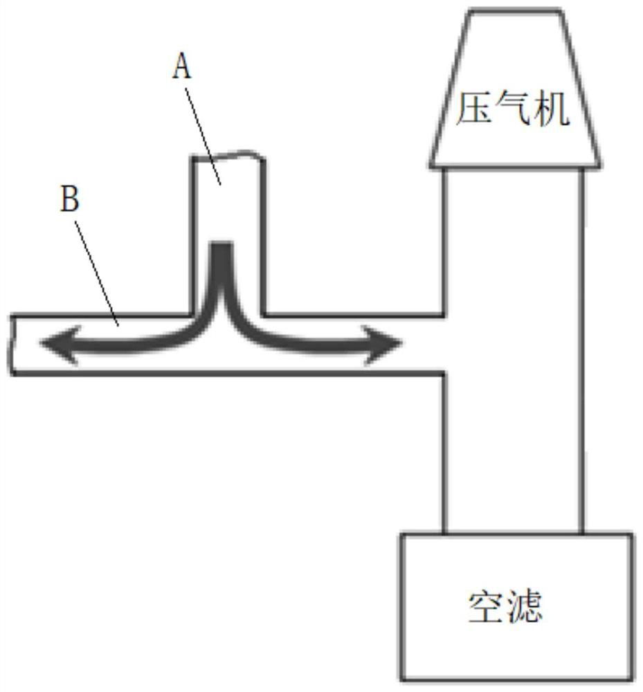
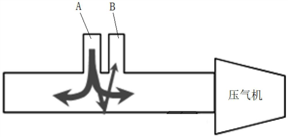
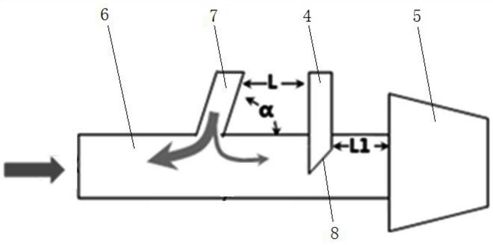
[0029] In the present invention, the distance between the ventilation pipe and the compressor is set to be smaller than the distance between the ventilation pipe and the anti-surge valve pipe, and one end of the ventilation pipe extends obliquely toward the direction of the compressor or is provided with a first oblique cut facing the compressor. It can slow down the impact of the anti-surge pipe airflow on the ventilation pipe, increase the...


PUM


Abstract

The invention discloses a structure for increasing negative pressure, relates to an engine, and solves the technical problem that the pressure of an existing crankcase cannot be steadily less than atmospheric pressure. The structure comprises a closed circulating crankcase, a supercharger and an oil-gas separation mechanism, wherein a vent pipe of the crankcase is connected with an air inlet passage at the front end of a gas compressor through the oil-gas separation mechanism, and the vent pipe is positioned between an anti-surge valve pipe and the gas compressor; the distance between the ventpipe and the gas compressor is smaller than the distance between the vent pipe and the anti-surge valve pipe; and one end of the vent pipe obliquely extends towards the direction of the gas compressor or is provided with a first oblique notch facing the gas compressor. The distance between the vent pipe and the gas compressor is smaller than the distance between the vent pipe and the anti-surge valve pipe, and one end of the vent pipe obliquely extends towards the direction of the gas compressor or is provided with the first oblique notch facing the gas compressor, so that the influence of airflow of an anti-surge pipe on the vent pipe can be reduced, suction force of the gas compressor to air in the crankcase is increased, and the pressure of the crankcase is steadily less than the atmospheric pressure.

Description

technical field [0001] The present invention relates to engines, and more particularly, it relates to a structure for increasing negative pressure. Background technique [0002] "GB 17691-2018 National Sixth Emission Standard for Heavy-Duty Vehicles" requires the crankcase ventilation system: "C.5.11 For the measurement of ignition engine crankcase emissions, the crankcase pressure should be measured at a suitable position during the entire test and training process, and the pressure measurement is accurate. The pressure should be within ±1kPa, and the crankcase pressure should not be greater than the atmospheric pressure", that is, the crankcase pressure of the gas engine should be kept as a negative pressure. Existing conventional crankcase ventilation systems include: adopting an open circulation system, adopting a centrifugal oil-gas separator, and adopting a closed circulation system. The open circulation system leads directly to the atmosphere and cannot form negative...

Claims


Application Information

Patent Timeline
Patent Type & Authority Applications(China)
IPC IPC(8): F01M13/02F01M13/04
CPCF01M13/021F01M13/04F01M2013/026F01M2013/027
Inventor 梁德浦林铁坚覃文刘肖毅何化朱雄磨小重周森
Owner GUANGXI YUCHAI MASCH CO LTD
Why Eureka
Try Eureka