Supercharge Your Innovation With Domain-Expert AI Agents!

Transformer fireproof device

A technology for fire protection devices and transformers, applied in the field of transformers, can solve problems such as explosion and complex structure, and achieve the effects of low failure rate and simple structure

Active Publication Date: 2020-12-04
NANJING SHUANGJING ELECTRICAL
View PDF9 Cites 2 Cited by
  • Summary
  • Abstract
  • Description
  • Claims
  • Application Information

AI Technical Summary

Problems solved by technology

[0003] The fireproof transformer of the prior art CN 103985529 B achieves the purpose of fire extinguishing by setting a closed cover, driving an air pump, an electric telescopic rod, a temperature sensor and a controller to cause a lack of oxygen in the area where the closed coil is located. There are a lot of electrical equipment and electrical components. When the temperature of the transformer is too high, these electrical equipment and electrical components may not all work normally. The strongly enclosed space formed by this scheme may cause explosion hazards when the temperature of the transformer continues to rise.

Method used


Image

  • Transformer fireproof device
  • Transformer fireproof device
  • Transformer fireproof device

Examples


Embodiment Construction

[0034] The following is further described in detail through specific implementation methods:

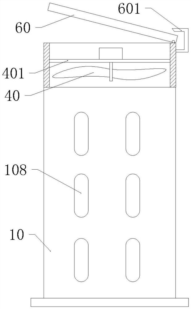
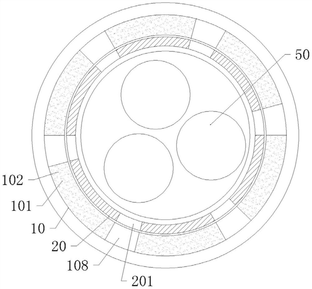
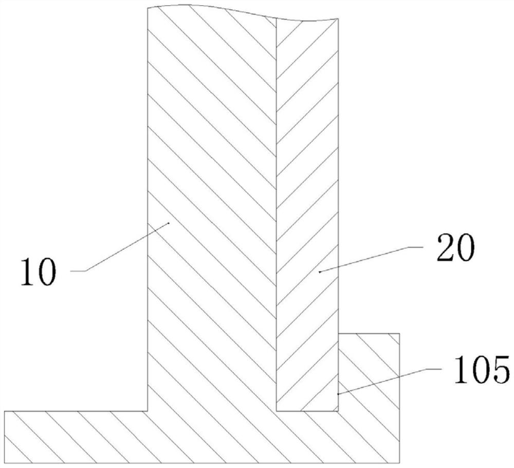
[0035] The reference signs in the drawings of the description include: outer cylinder 10, high pressure cavity 101, dry powder fire extinguishing agent 102, spout 103, blocking block 104, annular slideway 105, stopper 106, first compression spring 107, outer vent 108 , chute 109, first compression spring 1091, limit slider 1092, inner cylinder 20, inner vent 201, notch 202, limit groove 203, limit post 204, fixed block 30, bimetal 301, ventilation Machine 40, fixed rod 401, transformer 50, cover plate 60, limit rod 601.

[0036] A kind of transformer 50 fire protection device, such as figure 1 , figure 2 As shown, it includes a vertically arranged inner cylinder 20 and an outer cylinder 10 sleeved outside the inner cylinder 20. The outer cylinder 10 and the inner cylinder 20 are both cylindrical in shape with openings at both ends. The inner cylinder 20 and the outer cylinder 10 a...


PUM


Abstract

The invention relates to the technical field of transformers, in particular to a transformer fireproof device which comprises an inner cylinder and an outer cylinder which are vertically arranged. Corresponding ventilation openings are formed in the inner cylinder and the outer cylinder, a high-pressure cavity is formed in the side wall of the outer cylinder and is filled with a dry powder extinguishing agent, and a sliding groove and a limiting sliding block are arranged on the side wall of the upper end of the outer cylinder along the diameter direction of the outer cylinder. A limiting groove matched with the limiting sliding block is formed in the top face of the inner cylinder, a bimetallic strip is arranged on the inner wall of the outer cylinder, and an annular sliding way matched with the lower portion of the inner cylinder is arranged at the lower portion of the outer cylinder. A check block is arranged in the annular sliding way, the inner cylinder is provided with a notch corresponding to the check block, and a compression spring is arranged between the notch and the check block. According to the scheme, the structure is simple and reliable, the generated fire can be effectively extinguished, and the explosion danger cannot be generated.

Description

technical field [0001] The invention relates to the technical field of transformers, in particular to a transformer fire protection device. Background technique [0002] The primary coil and secondary coil of the existing dry-type transformer are sequentially wound on a single coil frame, and the iron core is fixed on the coil frame. In order to avoid leakage or other accidents, an insulating layer is usually provided between the iron core and the coil. When the coil is working, it will generate heat and bake the insulating layer. With long-term work, the insulating layer will age, and its fire resistance and insulation will be greatly reduced. When the coil temperature continues to rise and accumulate, it will cause local temperature to rise and cause a fire. . [0003] The fireproof transformer of the prior art CN 103985529 B achieves the purpose of fire extinguishing by setting a closed cover, driving an air pump, an electric telescopic rod, a temperature sensor and a co...

Claims


Application Information

Patent Timeline
IPC IPC(8): H01F27/00H01F27/02H01F27/08A62C3/16
CPCA62C3/16H01F27/00H01F27/022H01F27/08
Inventor 高伟军
Owner NANJING SHUANGJING ELECTRICAL
Features
  • R&D
  • Intellectual Property
  • Life Sciences
  • Materials
  • Tech Scout
  • Unparalleled Data Quality
  • Higher Quality Content
  • 60% Fewer Hallucinations
Learn More