Distance sensor pixel array structure, distance sensor and working method

A distance sensor and pixel array technology, applied in the sensor field, can solve the problems of mobile phone shutdown, high power consumption, AR and VR cannot be popularized, etc., and achieve the effect of reducing transmission power, reducing power consumption, and promoting popularization.

Pending Publication Date: 2020-12-04
上海大芯半导体有限公司
View PDF0 Cites 4 Cited by
  • Summary
  • Abstract
  • Description
  • Claims
  • Application Information

AI Technical Summary

Problems solved by technology

When the application is used in mobile phones and pads, such as AR and VR applications, it needs to be turned on for a long time, such as an application of 1 hour, but the power consumption is too large, and it is easy to cause the mobile phone to shut down. Therefore, AR and VR have not been popularized at present.

Method used


Image

  • Distance sensor pixel array structure, distance sensor and working method
  • Distance sensor pixel array structure, distance sensor and working method
  • Distance sensor pixel array structure, distance sensor and working method

Examples


Embodiment 1

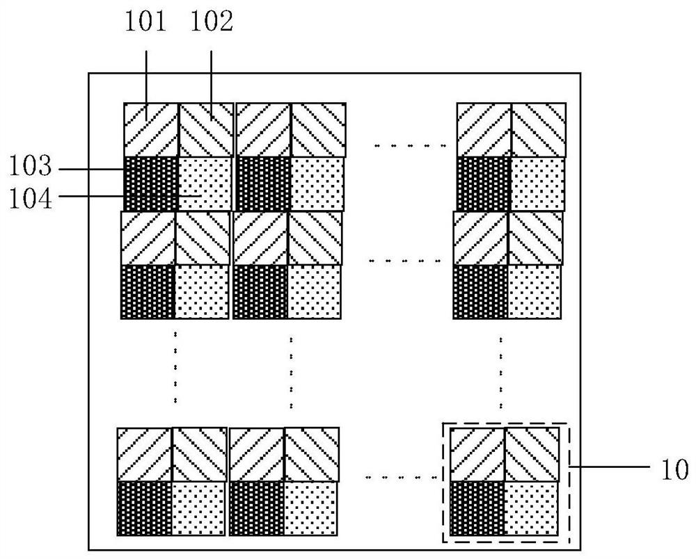
[0037] Embodiment 1 of the present invention provides a distance sensor pixel array structure. The implementation details of this embodiment will be specifically described below in conjunction with the accompanying drawings. The following content is only implementation details provided for easy understanding, and is not necessary for implementing this solution. Please refer to image 3 , this example includes:

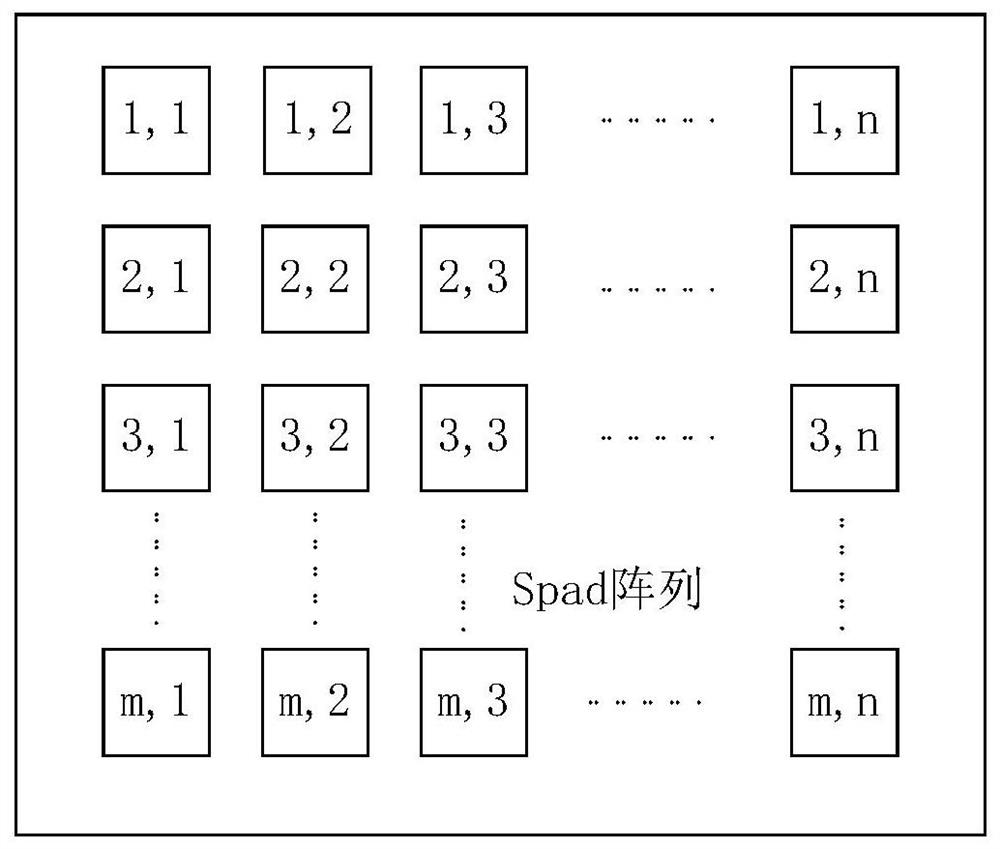
[0038] A plurality of pixel units are arranged in an array, and some of the pixel units are turned on at the same time.

[0039] In this embodiment, adjacent i×j pixel units form a group 10 , and the distance sensor pixel array structure includes the plurality of groups 10 .

[0040] For example, each group 10 is a combination of 2×2 pixel units.

[0041] Typically, each group can be identical.

[0042] In addition, each group can also be in other forms, such as 2×3, 3×3, etc. In this embodiment, each group does not need to be too complicated.

[0043] Taking a si...

Embodiment 2

[0046] Embodiment 2 of the present invention provides a distance sensor, which may be further optimized or improved on the basis of Embodiment 1. The implementation details of this embodiment are described in detail below, and the following content is only implementation details provided for easy understanding, and is not necessary for implementing this solution. This example includes:

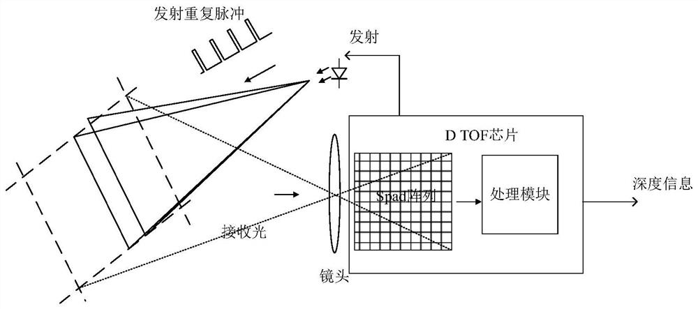
[0047] A transmitting end and a receiving end, the receiving end includes a plurality of pixel units arranged in an array; some of the pixel units are irradiated by the light spot emitted by the transmitting end with normal power, and the irradiated pixel units are in an on state.

[0048] Therefore, in the embodiment of the present invention, only the elements in the turned-on state will be irradiated, so that the utilization rate of the transmitting end can be maximized, and the waste of transmitting power consumption can be avoided.

Embodiment 3

[0050] Embodiment 3 of the present invention is a distance sensor, which can be further optimized or improved on the basis of Embodiment 2. The implementation details of this embodiment will be specifically described below in conjunction with the accompanying drawings. The following content is only implementation details provided for easy understanding, and is not necessary for implementing this solution. Please refer to Figure 4 and Figure 5 , this example includes:

[0051] For example, the emitting end can be divided into multiple light-emitting areas, such as Figure 4 It schematically shows the light emitting area 1, the light emitting area 2, the light emitting area 3 and the light emitting area 4, and different light emitting areas can emit light at different time periods. The receiving end can be divided into multiple receiving areas, such as Figure 5 Receiving area 1, receiving area 2, receiving area 3 and receiving area 4 are schematically shown, and different...


PUM


Abstract

The invention discloses a distance sensor pixel array structure, a distance sensor and a working method. The distance sensor comprises an emitting end and a receiving end, wherein the receiving end comprises a plurality of pixel units arranged in an array, part of the pixel units are irradiated by light spots emitted from the emitting end at normal power, and the irradiated pixel units are in an on state. Therefore, during working, the on state of the emitting end can be purposefully controlled, for example, the emitting end only irradiates part of a region, and other regions are not irradiated, so that the emitting power can be greatly reduced, namely, the power consumption of the TOF is greatly reduced, the popularization of the TOF is promoted, and the popularization of AR and VR is indirectly promoted.

Description

technical field [0001] The invention relates to the technical field of sensors, in particular to a distance sensor pixel array structure, a distance sensor and a working method. Background technique [0002] With the gradual realization of AR / VR technology on mobile phones, the 3D D TOF (direct time of flight) distance sensor, as the core chip, has gradually become the standard configuration of mobile phones just like the two-dimensional image sensor. However, the power consumption is too high, which seriously affects its application on mobile phones, thereby hindering the promotion of AR / VR technology. [0003] The existing D TOF distance sensor consumes too much power, so when it is used in mobile phones, the distance is limited and the use time is limited, which affects the user's use effect. Face unlocking, payment and other operations that do not need to be turned on for a long time can only be performed on the front camera of the mobile phone. When the application is...

Claims


Application Information

Patent Timeline
Patent Type & Authority Applications(China)
IPC IPC(8): H01L27/146G01S7/484G01S7/4861G01S7/4911G01S7/4913G01S17/08G01S17/894
CPCG01S7/484G01S7/4861G01S7/4911G01S7/4913G01S17/08G01S17/894H01L27/14605H01L27/14643
Inventor 东尚清
Owner 上海大芯半导体有限公司
Why Eureka
Try Eureka