Device and method for twisting end part of stator of flat-wire motor

A motor stator and flat wire technology, applied in the field of motor assembly equipment, can solve the problems of manual tooling, affecting the production rhythm, increasing the difficulty of turning heads, etc., and achieve the effect of improving the expansion efficiency, improving the accuracy and saving manpower

Active Publication Date: 2020-12-04
ANHUI JEE AUTOMATION EQUIP CO LTD
View PDF16 Cites 7 Cited by
  • Summary
  • Abstract
  • Description
  • Claims
  • Application Information

AI Technical Summary

Problems solved by technology

[0003] As the new energy vehicle drive motor stator requires more and more layers of flat wires (currently up to 8 layers), the mold slots corresponding to the stator flat wires have also doubled, and if a wire cannot be inserted into the mold, it will cause The failure of twisting the head, more layers of stator flat wires greatly increases the difficulty of turning the head, and it is required to ensure the accuracy of the insertion line during production
[0004] The existing technical solutions are aimed at a small number of stator flat wire layers, generally 4 layers, and most of them are semi-automatic equipment. Manual tooling is required for the expansion, and manual assistance and confirmation are required when the flat wire is inserted into the mold.
[0005] However, manual tooling is used for flaring, which is inefficient and less stable. During the flaring process, it is

Method used


Image

  • Device and method for twisting end part of stator of flat-wire motor
  • Device and method for twisting end part of stator of flat-wire motor
  • Device and method for twisting end part of stator of flat-wire motor

Examples


Example Embodiment

[0054] It should be noted that the embodiments in the present application and the features of the embodiments may be combined with each other in the case of no conflict. The present invention will be described in detail below with reference to the accompanying drawings and in conjunction with the embodiments.

[0055] Figure 1-Figure 17 Some embodiments according to the invention are shown.
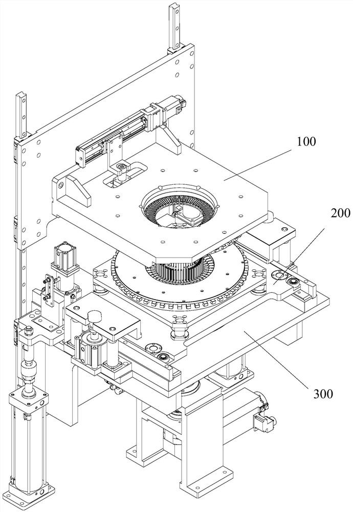
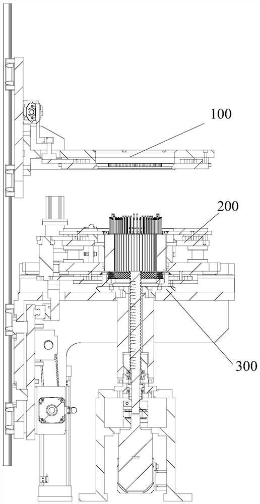
[0056] like figure 1 , figure 2 , Figure 9 As shown, a device for twisting the end of the stator of a flat wire motor includes a base, a lower table support mechanism 300, a flaring mechanism 100, a fixture positioning mechanism 200, and a twisting mechanism, wherein the fixture positioning mechanism 200 is used for positioning and transporting The stator 500 and the sliding table supporting mechanism 300 are used to support the positioning fixture positioning mechanism 200 and control its up and down movement.

[0057] The flaring mechanism 100 is used for flaring the stator flat...


PUM


Abstract

The invention discloses a device for twisting the end part of a stator of a flat-wire motor. The device comprises: a clamp positioning mechanism used for positioning and transporting the stator; a flaring mechanism used for enabling the end part of a stator coil to move along the radial direction of a stator iron core; an end twisting mechanism used for twisting a flared flat wire; and a base usedfor mounting the end twisting mechanism and the flaring mechanism. The invention further provides a method for twisting the end part of the stator of the flat-wire motor. The method comprises the steps of positioning, primary twisting and secondary twisting. The invention also discloses a method for layered flaring of the end part of the stator of the flat-wire motor. The method comprises the steps of positioning, primary flaring, secondary flaring and the like. By arranging the flaring mechanism, a contact surface of a flaring part and a flat wire is small, so it is guaranteed that each wirecan be inserted into an end twisting die, the accuracy of wire insertion is guaranteed, and the percent of pass of twisted ends is increased; and full-automatic flaring is achieved, so manpower is saved, flaring efficiency is improved, the accuracy of wire insertion can be guaranteed, and the percent of pass of twisting ends is increased.

Description

technical field [0001] The invention relates to the technical field of motor assembly equipment, in particular to a device and method for twisting the stator end of a flat wire motor. Background technique [0002] As the country vigorously promotes energy conservation and environmental protection, new energy vehicles have developed rapidly. As the core component of new energy vehicles, the drive motor plays a vital role. Wherein, during the assembly process of the driving motor, it is necessary to perform layered twisting on the stator of the driving motor. [0003] As the new energy vehicle drive motor stator requires more and more layers of flat wires (currently up to 8 layers), the mold slots corresponding to the stator flat wires have also doubled, and if a wire cannot be inserted into the mold, it will cause The failure of twisting the head, more layers of stator flat wires greatly increases the difficulty of turning the head, and it is required to ensure the accuracy...

Claims


Application Information

Patent Timeline
IPC IPC(8): H02K15/02H02K15/00
CPCH02K15/0087H02K15/02
Inventor 刘蕾石爱文吴洋胡冬宝沐俊宏
Owner ANHUI JEE AUTOMATION EQUIP CO LTD
Why Eureka
Try Eureka