Long-distance lossless transmission display and control system

A lossless transmission and control system technology, applied in the field of data transmission, can solve the problems of feedback error, time-consuming and laborious, low efficiency, etc., and achieve the effect of improving the maintenance efficiency and the accuracy of signal feedback

Inactive Publication Date: 2020-12-04
AVIC HUADONG OPTOELECTRONICS (SHANGHAI) CO LTD
View PDF10 Cites 1 Cited by
  • Summary
  • Abstract
  • Description
  • Claims
  • Application Information

AI Technical Summary

Problems solved by technology

Generally, this kind of maintenance requires the cooperation of multiple people, which not only has the problems of time-consuming, laborious and low efficiency, but also has the delay of the detected data feedback. Considering the large noise environment of the on-site detection, there may even be feedback errors.

Method used


Image

  • Long-distance lossless transmission display and control system
  • Long-distance lossless transmission display and control system
  • Long-distance lossless transmission display and control system

Examples


Embodiment 1

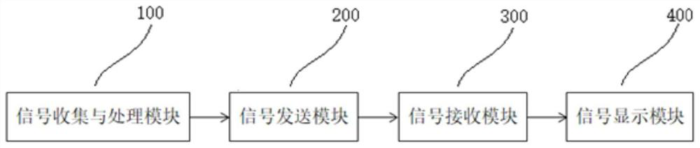
[0042] Such as figure 1 As shown, a long-distance lossless transmission display and control system is used for aircraft inspection equipment, including a signal collection and processing module 100 , a signal sending module 200 , a signal receiving module 300 and a signal display module 400 .

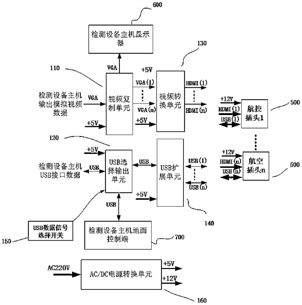
[0043] Such as figure 2As shown, the signal collection and processing module 100 is used to collect and process the original signal output by the detection device, that is, collect the analog VGA video data and USB data output by the detection device, copy the analog VGA video data into multiple channels, and then convert them into Multi-channel HDMI digital video data output, while expanding USB data to multiple outputs. Specifically, the signal collection and processing module 100 includes a video duplication unit 110 , a USB selection output unit 120 , a video conversion unit 130 , a USB extension unit 140 , and an AC / DC power conversion unit 160 . The video duplication unit 110 d...

Embodiment 2

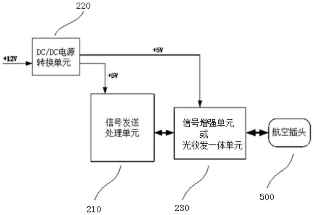
[0058] The difference between this embodiment and Embodiment 1 is that an integrated optical transceiver unit is used instead of the signal enhancement unit and the signal restoration unit. That is, both the signal sending module 200 and the signal receiving module 300 further include an integrated optical transceiver unit. The signal collection and processing module 100, the signal sending module 200, and the signal receiving module 300 are connected through optical fibers.

[0059] The optical transceiver integrated unit is an important device in the optical fiber communication system, which is responsible for converting the received optical signal into an electrical signal, or converting the input electrical signal into a stable optical signal at a corresponding rate. It is generally composed of optoelectronic devices, functional circuits and optical interfaces. The optoelectronic devices include two parts: transmitting and receiving.

[0060] The DC / DC power conversion un...


PUM


Abstract

The invention discloses a long-distance lossless transmission display and control system, which is used for aircraft detection equipment, and comprises a signal collection and processing module whichcomprises a video copying unit, a USB selection output unit, a video conversion unit, a USB expansion unit and an AC/DC power supply conversion unit and is used for collecting and processing originalsignals output by the detection equipment; a signal sending module that comprises a signal sending processing unit and a DC/DC power supply conversion unit, and is used for receiving an output signalof the signal collecting and processing module, processing the output signal into a high-speed serial signal and sending the high-speed serial signal; a signal receiving module which comprises a signal receiving and processing unit and is used for receiving the high-speed serial signal sent by the signal sending module and carrying out unpacking recovery; and a signal display module. According tothe invention, maintainers in the aircraft can obtain real-time and accurate data signal feedback, and the maintenance efficiency and the signal feedback accuracy are improved.

Description

technical field [0001] The invention relates to the technical field of data transmission, in particular to a long-distance lossless transmission display and control system. Background technique [0002] At present, during aircraft maintenance, it is necessary to use special aircraft testing equipment to conduct online maintenance on the ground to check the operating status of each system of the aircraft, including the measurement, inspection and correction of various parameters. Due to the complexity of the various systems of the aircraft, personnel are required to operate the airborne equipment in the cockpit or cabin during maintenance, and at the same time, other specialized personnel are required to observe the system operating status parameters displayed by the corresponding aircraft testing equipment on the ground. Whether it is normal, and needs to be timely fed back to the operator in the cockpit or engine room for the next step. Generally, this kind of maintenance ...

Claims


Application Information

Patent Timeline
Patent Type & Authority Applications(China)
IPC IPC(8): H04N7/18H04N5/268H04N5/765
CPCH04N7/18H04N5/268H04N5/765
Inventor 李旭管科康涛郎立国
Owner AVIC HUADONG OPTOELECTRONICS (SHANGHAI) CO LTD
Why Eureka
Try Eureka