Method for formation lithology analysis while drilling in gas drilling

A technology of gas drilling and formation lithology, which is applied in material analysis using radiation diffraction, earthwork drilling, wellbore/well components, etc., which can solve the problems of high analysis cost, inability to analyze formation while drilling, and inability to accurately determine mineral components And other issues

Inactive Publication Date: 2012-10-10
SOUTHWEST PETROLEUM UNIV
View PDF3 Cites 17 Cited by
  • Summary
  • Abstract
  • Description
  • Claims
  • Application Information

AI Technical Summary

Problems solved by technology

[0008] First, this method does not have any timeliness, it cannot analyze the formation while drilling, it cannot describe the formation section in a timely and effective manner, and it cannot guide the drilling construction
[0009] Second, the analysis cost of this method is relatively high
However, since the XRF analysis method uses elements to identify lithology, the accuracy of this method is extremely low, because the same several elements can form different minerals, and minerals are mixtures with complex components, and the element content in the same mineral also changes. It is impossible to accurately determine the mineral composition from the elemental point of view
Since the above method uses an energy dispersive X-ray fluorescence analyzer, which analyzes elements, it cannot obtain the various mineral components contained in the rock formation, and cannot quickly determine the formation profile according to the mineral composition of the rock formation.
In the above method, the sample preparation process is complicated and the required conditions are harsh, which is not conducive to timely analysis of cuttings, and the analysis cycle is still long
In addition, the above patent documents do not provide any technical solutions or technical revelations that can quickly determine the mineral components contained in the rock formation

Method used


Image

  • Method for formation lithology analysis while drilling in gas drilling
  • Method for formation lithology analysis while drilling in gas drilling
  • Method for formation lithology analysis while drilling in gas drilling

Examples


Embodiment Construction

[0114] The present invention will be further described below in conjunction with the accompanying drawings and specific embodiments.

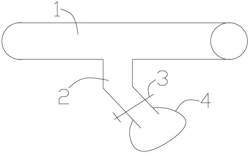
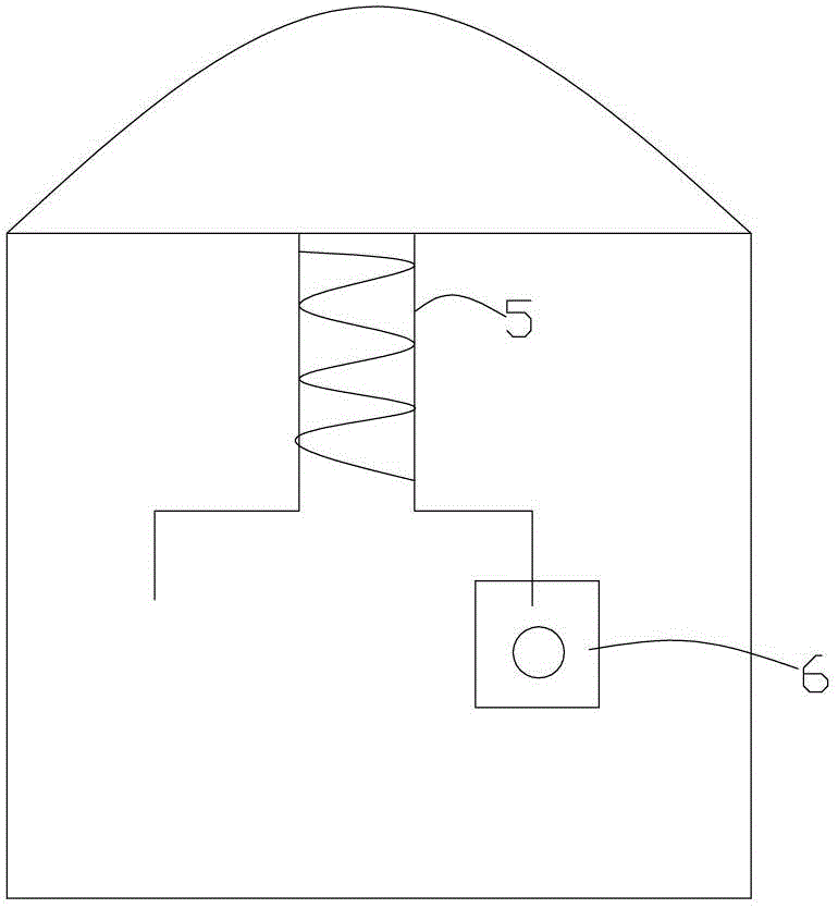
[0115] Such as Figure 7 Shown, the gas drilling of the present invention analyzes the method for stratum lithology while drilling,

[0116] Determination of cuttings late arrival time;

[0117] Obtain the cuttings corresponding to the depth of the well according to the late arrival time of the cuttings. The cuttings are obtained every 1 to 2 meters according to the drilling depth from shallow to deep;

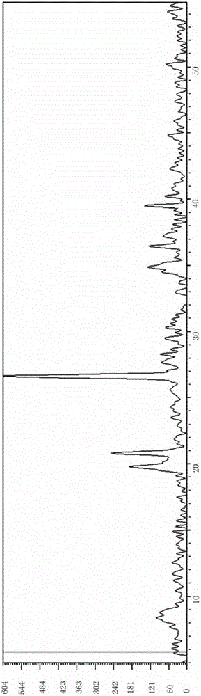
[0118] X-ray diffraction analysis of the cuttings is carried out at the drilling site after each cuttings acquisition, and the X-ray diffraction data of the cuttings are obtained, and the lithology is judged at the drilling site through the X-ray diffraction data: firstly, the X-ray diffraction pattern is obtained according to the X-ray diffraction data, Then compare the X-ray diffraction pattern with the mineral composition database to obtai...


PUM

PropertyMeasurementUnit
densityaaaaaaaaaa

Abstract

The invention provides a method for formation lithology analysis while drilling in gas drilling. The method for formation lithology analysis while drilling in gas drilling can be used for quick and accurate analysis of rock cuttings returned in gas drilling. The method mainly includes determining lag time of cuttings, acquiring the cuttings, performing field X-ray diffraction analysis and determining lithology. By the method, data of mineral components in formation can be acquired quickly on the drilling field. By the method compared with the prior art, analysis cycle of cutting samples can be shortened evidently, lithology determination is quick, and accuracy in lithology determination is improved. In addition, real-time analysis along drilling progress can be achieved by the method, lithologic profile of the formation can be obtained in real time, lithology determination can be fed back to technicians on the drilling field immediately, and the technicians on the field can take correspond measures in time to avoid drilling accidents.

Description

technical field [0001] The invention relates to a lithology analysis method applied in the field of oil and gas development, in particular to a method for analyzing formation lithology while drilling a gas well. Background technique [0002] Gas drilling is a drilling process that uses gas (air, nitrogen, etc.) as drilling fluid. It has the characteristics of greatly increasing drilling speed, shortening drilling cycle, and effectively discovering and protecting oil and gas layers. Especially for low-permeability oil and gas fields, if ordinary drilling methods are used, the drilling fluid will cause water lock damage to the rock formation, which will affect the normal production of the oil and gas fields. Therefore, the use of gas drilling is an effective way to develop low-permeability oil and gas fields, and has become one of the leading technologies for the exploration and development of low-permeability oil and gas fields in my country. [0003] In the exploration and ...

Claims


Application Information

Patent Timeline
Patent Type & Authority Applications(China)
IPC IPC(8): E21B49/02E21B49/00G01N23/20
Inventor 李皋孟英峰刘厚彬万里平魏纳陈一健李永杰汪传磊刘博伟严俊涛刘金龙
Owner SOUTHWEST PETROLEUM UNIV
Why Eureka
Try Eureka