Pinecone picking device for forest area
A forest area and installation board technology, applied in the direction of picking machines, agricultural machinery and implements, etc., can solve problems such as blockage, device does not have dredging function, and cannot be picked, and achieves the effect of ensuring smooth movement
- Summary
- Abstract
- Description
- Claims
- Application Information
AI Technical Summary
Problems solved by technology
Method used
Image
Examples
specific Embodiment approach 1
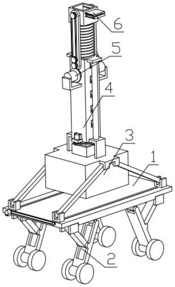
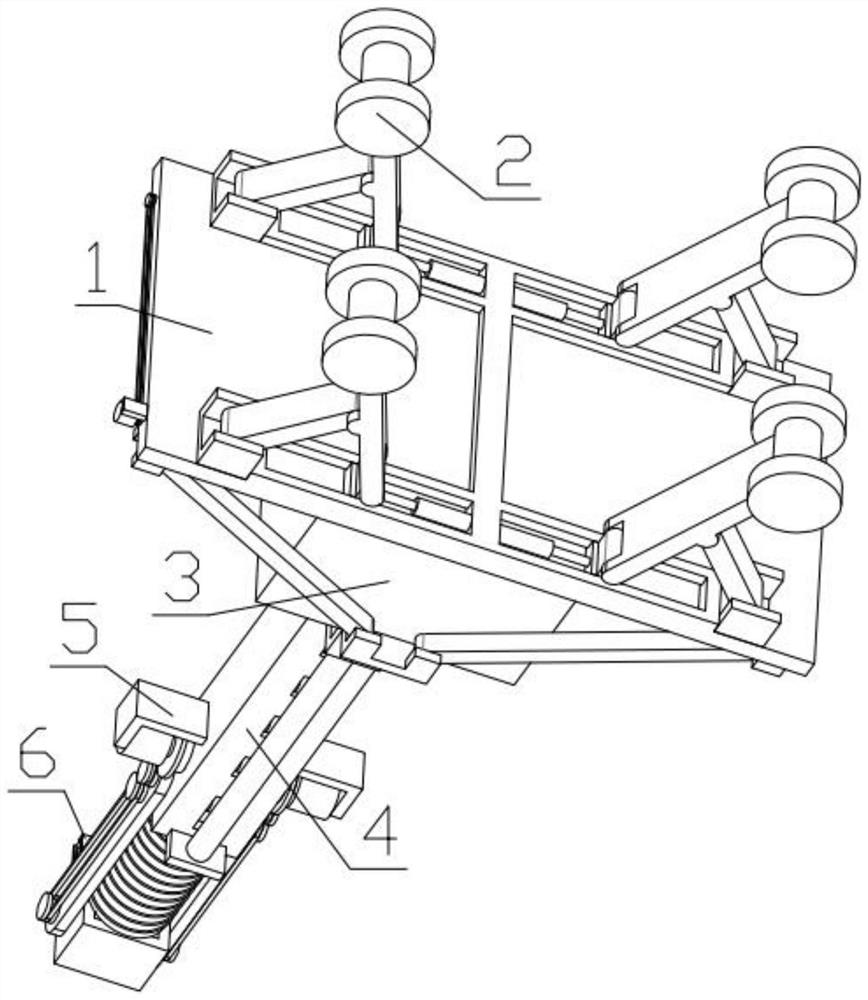
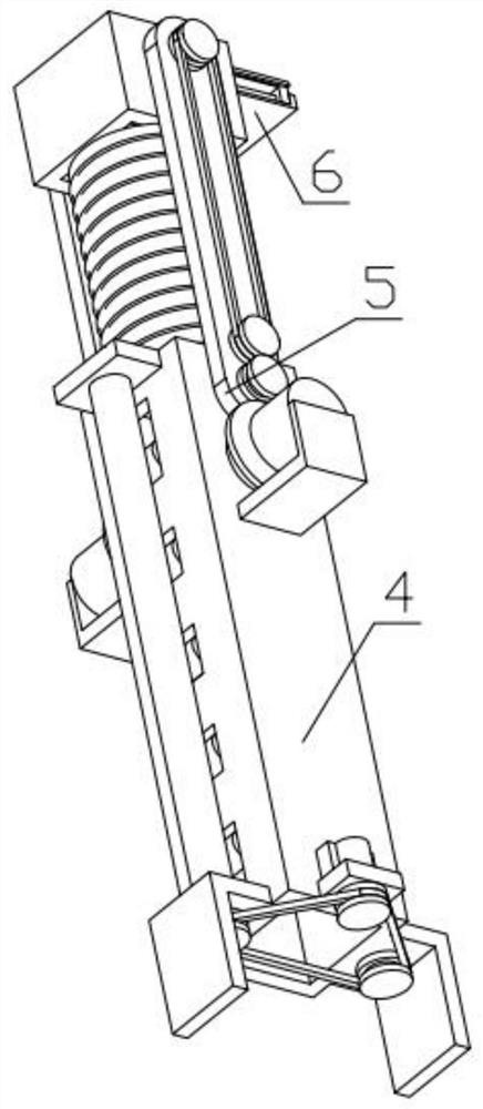
[0038] Combine below Figure 1-14 Illustrate this embodiment, a kind of forest area pine tower picking device, comprise middle mounting plate 1, moving mechanism 2, lifting mechanism 3, buffer mechanism 4, swing picking mechanism 5 and cutting assembly 6, the number of described moving mechanism 2 There are four, which are evenly fixed on the bottom of the middle mounting plate 1, the lifting mechanism 3 is fixed on the middle mounting plate 1, the buffer mechanism 4 is fixed on the lifting mechanism 3, and the swing picking mechanism 5 is fixed on the buffer mechanism 4 On, the cutting assembly 6 is fixedly installed on the swing picking mechanism 5 .
specific Embodiment approach 2
[0040] Combine below Figure 1-14 This embodiment will be described. This embodiment will further describe the first embodiment. The moving mechanism 2 includes a hydraulic cylinder 2-1, a push slider 2-2, a supporting leg 2-3, an adjustment arm 2-4, and a U-shaped hinge. Part 2-5, moving wheel 2-6, hydraulic cylinder 2-1 is fixedly installed in the groove provided by the middle mounting plate 1, the output end of hydraulic cylinder 2-1 is fixedly installed on the push slider 2-2, pushes the slider 2-2 is slidingly installed in the groove provided by the middle mounting plate 1, and the sliding block 2-2 is pushed to be hinged with the support leg 2-3, and the other end of the support leg 2-3 is equipped with a moving wheel 2-6, and the adjustment arm 2 One end of -4 is hinged on the support leg 2-3, the other end of the adjustment arm 2-4 is hinged on the U-shaped hinge 2-5, and the U-shaped hinge 2-5 is fixedly installed on the middle mounting plate 1.
specific Embodiment approach 3
[0042] Combine below Figure 1-14 Describe this embodiment, this embodiment will further explain the first embodiment, the lifting mechanism 3 includes a storage box 3-1, a lifting arm 3-2, a threaded sliding foot 3-3, a transmission sprocket 3-4, a transmission chain 3-5, lifting motor 3-6, two-way threaded rod 3-7, box door 3-8, box door 3-8 is installed on the storage box 3-1, storage box 3-1 is hinged with lifting arm 3-2 , the other end of the lifting arm 3-2 is hinged on the threaded sliding foot 3-3, and the threaded sliding foot 3-3 is slidably installed in the groove provided by the middle mounting plate 1, and the threaded sliding foot 3-3 is connected with the two-way threaded rod 3- 7 threaded connection, one end of the two-way threaded rod 3-7 is rotatably installed in the groove provided on the intermediate mounting plate 1, the other end of the two-way threaded rod 3-7 passes through the intermediate mounting plate 1 and is fixedly installed with the transmissio...
PUM
 Abstract
Description
Claims
Application Information
 - R&D
- Intellectual Property
- Life Sciences
- Materials
- Tech Scout
- Unparalleled Data Quality
- Higher Quality Content
- 60% Fewer Hallucinations
Browse by: Latest US Patents, China's latest patents, Technical Efficacy Thesaurus, Application Domain, Technology Topic, Popular Technical Reports.
© 2025 PatSnap. All rights reserved.Legal|Privacy policy|Modern Slavery Act Transparency Statement|Sitemap|About US| Contact US: help@patsnap.com


