Efficient and stable test tube shaking device

A test tube, stable technology, applied in the field of efficient and stable test tube shaking device, can solve the problems of low efficiency and single shaking method, and achieve the effect of ensuring the solution

Inactive Publication Date: 2020-12-08
师鹏举
View PDF8 Cites 1 Cited by
  • Summary
  • Abstract
  • Description
  • Claims
  • Application Information

AI Technical Summary

Problems solved by technology

[0005] The object of the present invention is to provide an efficient and stable test tube shaking device with high efficiency and good shaking effect for the problems of low efficiency and single shaking method

Method used


Image

  • Efficient and stable test tube shaking device
  • Efficient and stable test tube shaking device
  • Efficient and stable test tube shaking device

Examples


Embodiment 1

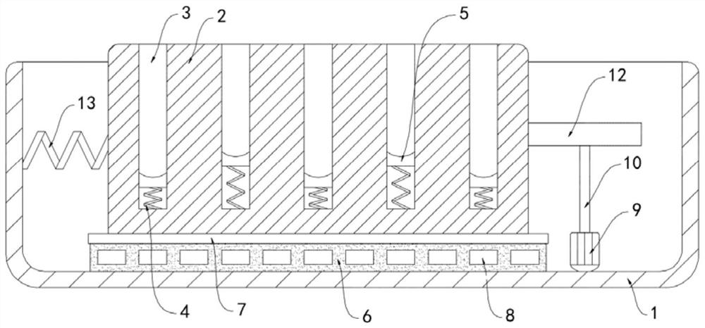
[0019] Such as Figure 1-2 As shown, an efficient and stable test tube shaking device includes a housing 1, the upper end of the housing 1 is open, and the upper surface of the shaking frame 2 is equidistantly provided with a plurality of placement grooves 3, and the bottom of the placement groove 3 passes through the The vibrating spring 4 is fixedly connected with a magnetic slider 5 , and the magnetic slider 5 is slidably connected with the side wall of the placement groove 3 .

[0020] The bottom of the housing 1 is fixedly connected with a fixed plate 6, the upper surface of the fixed plate 6 is equipped with a slide rail 7, the shaking frame 2 is arranged on the upper surface of the slide rail 7 and is slidably connected with the slide rail 7, and the fixed plate 6 is equidistant A plurality of permanent magnet blocks 8 matching the magnetic slider 5 are embedded, and the magnetism between two adjacent permanent magnet blocks 8 is opposite.

[0021] The side wall of the...

Embodiment 2

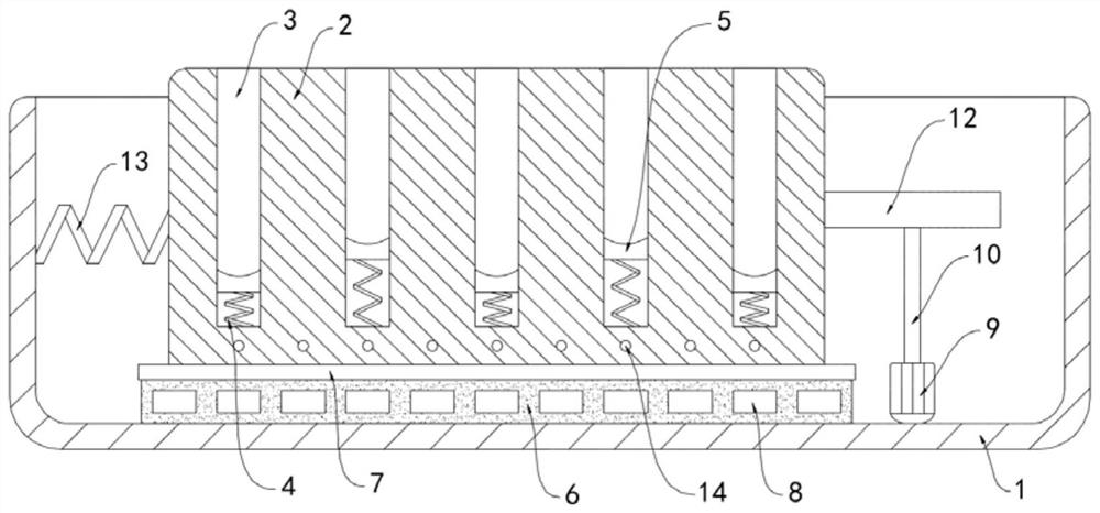
[0025] Such as image 3 As shown, the difference between this embodiment and Embodiment 1 lies in that: the shaker frame 2 is embedded with multi-strand closed coils 14 , and the multi-strand closed coils 14 are wound along the horizontal direction.

[0026] In this embodiment, during the reciprocating sliding of the shaking frame 2 in the horizontal direction, the closed coil 14 continuously cuts the magnetic induction line of the permanent magnet block 8 to generate an induced current, and the current generates heat to heat the test tube, which can promote the chemical reaction in the test tube. The reaction is carried out quickly, which speeds up the progress of the experiment.


PUM


Abstract

The invention belongs to the field of chemical experiment equipment, and particularly relates to an efficient and stable test tube shaking device. The device comprises a shell, the upper end of the shell is open, a shaking frame is arranged in the shell, a plurality of containing grooves are formed in the upper surface of the shaking frame at equal intervals, and magnetic sliding blocks are fixedly connected to the bottoms of the containing grooves through vibration springs. The bottom of the shell is fixedly connected with a fixing plate. A sliding rail is installed on the upper surface of the fixing plate. The shaking frame is arranged on the upper surface of the sliding rail and is in sliding connection with the sliding rail. A plurality of permanent magnet blocks matched with the magnetic sliding blocks are embedded in the fixing plate at equal intervals. The magnetism between every two adjacent permanent magnet blocks is opposite, and a driving mechanism used for driving the shaking-up frame to shake is arranged on the side wall of the shaking frame. The shaking operation of the test tubes in the transverse direction and the longitudinal direction can be achieved at the same time, and it is ensured that solutions in the test tubes are uniform and experimental results are stable.

Description

technical field [0001] The invention belongs to the field of chemical experiment equipment, in particular to an efficient and stable test tube shaking device. Background technique [0002] When conducting experiments in chemical laboratories, it is often necessary to use test tubes for rapid solution preparation or chemical reactions. During use, the test tubes need to be shaken continuously to ensure that the solvent and solute are evenly mixed to promote the forward reaction. [0003] The traditional way of shaking test tubes is mostly by holding the test tube, exerting force on the wrist, and shaking the test tube back and forth. This method is more energy-consuming, time-consuming, and inefficient, which increases the burden of chemical experiment operations and cannot be used for multiple control test tubes. At the same time, the shaking operation increases the uncertainty of the experimental results; part of the shaking operation is carried out by the test tube shaking...

Claims


Application Information

Patent Timeline
Patent Type & Authority Applications(China)
IPC IPC(8): B01F11/00B01F15/06
CPCB01F31/201B01F35/90B01F2035/99
Inventor 师鹏举
Owner 师鹏举
Why Eureka
Try Eureka