Automatic installation device for evaporator cooling fins
An automatic installation and heat sink technology, which is applied in the direction of assembly machines, metal processing equipment, manufacturing tools, etc., can solve the problems of low production efficiency, time-consuming and laborious, etc.
- Summary
- Abstract
- Description
- Claims
- Application Information
AI Technical Summary
Problems solved by technology
Method used
Image

Examples
specific Embodiment approach 1
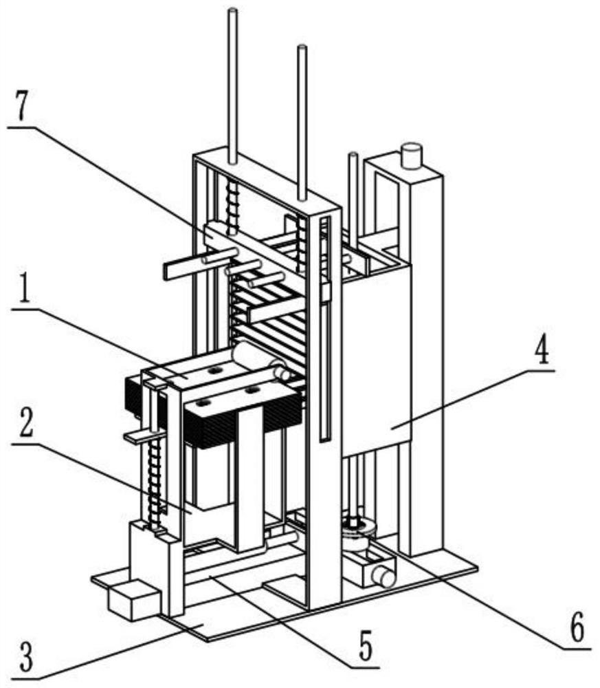
[0028] Such as Figure 1-8 As shown, an automatic installation device for evaporator cooling fins includes a cooling fin 1, a cooling fin carrying and pushing mechanism 2, a chassis 3, a fin arrangement mechanism 4, an extrusion mechanism 5, a condensation pipe installation mechanism 6 and an auxiliary extrusion mechanism 7, The heat sink carrying push mechanism 2 is fixedly connected to the chassis 3, the fin row mechanism 4 is threadedly connected to the bottom frame 3, the heat sink 1 is placed on the heat sink carrying push mechanism 2, and the heat sink 1 Slidingly connected in the fin arrangement mechanism 4, the extruding mechanism 5 is slidably connected to the lower end of the heat sink carrying push mechanism 2, the condensation pipe installation mechanism 6 is threadedly connected to the lower end of the extruding mechanism 5, and the auxiliary extruding mechanism 5 The pressing mechanism 7 is slidably connected to the upper end of the extruding mechanism 5 .
[00...
specific Embodiment approach 2
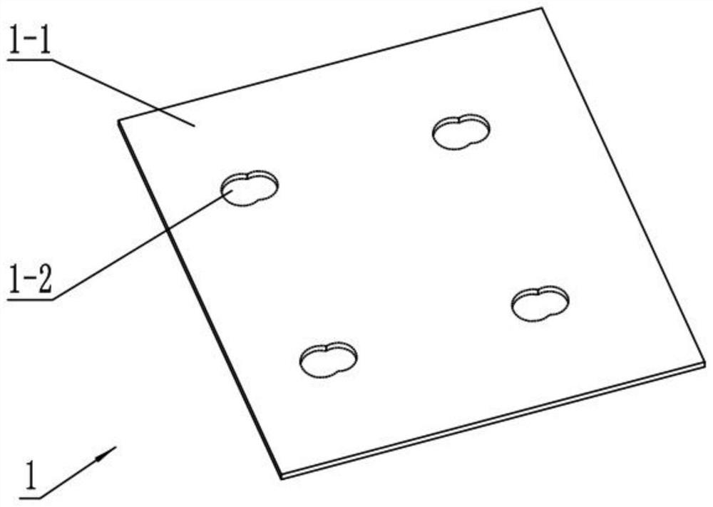
[0031] Such as Figure 1-8 As shown, the heat sink 1 includes a heat sink body 1-1 and a gourd-shaped hole 1-2, and the heat sink body 1-1 is provided with a plurality of gourd-shaped holes 1-2.
[0032] The gourd-shaped hole 1-2 on the heat sink body 1-1 is divided into a large hole end and a small hole end. The large hole end is used to pass through the condensation pipe, and then the condensation pipe is squeezed into the small hole end, so that the heat sink body 1-1 is fixed with the condenser tube.
specific Embodiment approach 3
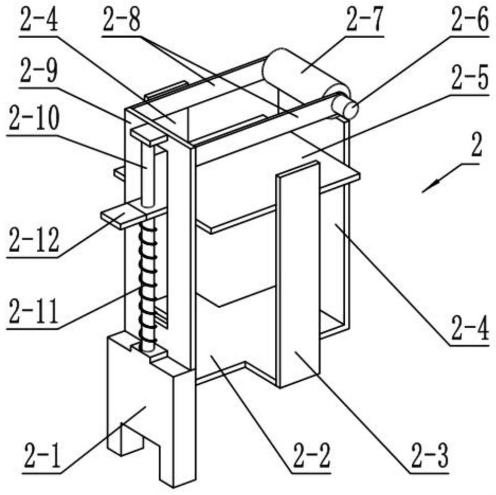
[0034] Such as Figure 1-8As shown, the heat sink carrying and pushing mechanism 2 includes a support base 2-1, a connecting plate 2-2, a side baffle 2-3, a front baffle 2-4, a carrying plate 2-5, and a supporting plate 2-9 And support sliding column 2-10, connecting plate 2-2 is fixedly connected on the front end face of support seat 2-1, and the left and right ends of connecting plate 2-2 are all fixedly connected with side baffle plate 2-3, and front baffle plate 2- 4 is fixedly connected to the front end of the connection plate 2-2, the support plate 2-9 is fixedly connected to the upper end of the support seat 2-1, the support sliding column 2-10 is fixedly connected to the rear end of the support plate 2-9, and the bearing plate 2-9 is fixedly connected to the upper end of the support seat 2-1. The rear end of 5 is slidably connected in the support plate 2-9 and is slidably connected with the support sliding column 2-10.
[0035] The carrying plate 2-5 is used for stack...
PUM
 Abstract
Description
Claims
Application Information