Viaduct bridge pavement edge vehicle anti-impact drainage protection structure

A technology for elevated bridges and protective structures, applied to bridges, bridge construction, bridge parts, etc., can solve problems such as damage, hidden dangers to driver's life safety, weakening of impact loads, etc., to improve the convenience of replacement, convenience and efficiency , to reduce the effect of hindering influence

Inactive Publication Date: 2020-12-08
安徽荣港建筑工程有限公司
View PDF6 Cites 3 Cited by
  • Summary
  • Abstract
  • Description
  • Claims
  • Application Information

AI Technical Summary

Problems solved by technology

[0007] The object of the present invention is to provide a kind of anti-impact and dredging protection structure for vehicles on the edge of the elevated bridge road surface, to solve the above-mentioned background technology. Partial fractures and damages, and it is inconvenient to maintain and replace the operation. After local structural damage occurs, secondary pouring and molding maintenance are required, which affects the normal driving of road traffic. The impact reaction force on the collision vehicle is large, making the collision position of the vehicle The damage is serious, causing hidden dangers to the driver's life safety, and it cannot weaken the impact load of the collision insufficiently, resulting in a large impact inertia of the load at the edge of the collision, which can easily cause double serious damage to the vehicle and bridge, and there is a problem of use defects

Method used


Image

  • Viaduct bridge pavement edge vehicle anti-impact drainage protection structure
  • Viaduct bridge pavement edge vehicle anti-impact drainage protection structure
  • Viaduct bridge pavement edge vehicle anti-impact drainage protection structure

Examples


Embodiment Construction

[0029] The following will clearly and completely describe the technical solutions in the embodiments of the present invention with reference to the accompanying drawings in the embodiments of the present invention. Obviously, the described embodiments are only some, not all, embodiments of the present invention. Based on the embodiments of the present invention, all other embodiments obtained by persons of ordinary skill in the art without making creative efforts belong to the protection scope of the present invention.

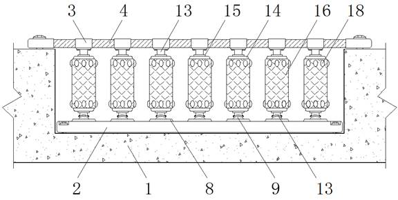
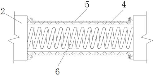
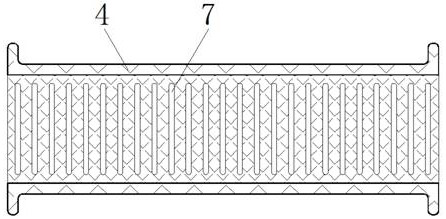
[0030] see Figure 1-8 , the present invention provides a technical solution: a vehicle anti-impact and dredging protection structure on the road surface of an elevated bridge, including a bridge deck edge 1, a positioning bar 2, a fixed block 3, a rubber tube 4, a rubber balloon membrane 5, a spring 6, an elastic Hole 7, fixed seat 8, ball ball 9, first magnet piece 10, second magnet piece 11, third magnet piece 12, connector 13, outer cylinder 14, sleeve 15,...


PUM


Abstract

The invention discloses a viaduct bridge pavement edge vehicle anti-impact drainage protection structure. The protection structure comprises a bridge deck edge, a positioning strip, fixing blocks andan outer cylinder, wherein the positioning strip and the fixing blocks are installed in the middle and at the top of the bridge deck edge through bolts correspondingly, rubber pipes are fixedly connected between the outer walls of the fixing blocks, the ends of the rubber pipes and the positioning strip are fixed through pins, rubber balloon films are arranged on the outer walls of the rubber pipes, fixing bases are fixed to the positioning strip in an embedded mode, balls are installed in the centers of the tops of the fixing bases in an embedded mode, and connecting pieces are fixed to the bottoms of the fixing blocks and the tops of the balls through bolts. According to the viaduct bridge pavement edge vehicle anti-impact drainage protection structure, overall disassembling, maintenanceand replacement of the structure are facilitated, the replacement convenience and efficiency are improved, the hindering influence of maintenance on traffic transportation is reduced, meanwhile, impact external force loads can be effectively weakened in a multiple mode, and the protection effect on bridges and vehicles is achieved.

Description

technical field [0001] The invention relates to the technical field related to the protection of viaducts, in particular to an anti-impact and dredging protection structure for vehicles at the road surface edge of viaducts. Background technique [0002] Viaduct is one of the existing rail transportation vehicles. By installing viaduct, it can greatly improve the space utilization rate of transportation, facilitate the interconnection of dislocation distribution between different roads, and maintain the stability of transportation work. To avoid traffic jams and potential safety hazards caused by the intersection distribution of cross lines between different road sections, a raised roadside structure is set at the edge of the road surface of the viaduct, and reinforced concrete pouring is used to carry out bridge road surface and The isolation of the suspended part achieves the effect of reminder and protection, and reduces the safety hazards such as falling of transportation...

Claims


Application Information

Patent Timeline
Patent Type & Authority Applications(China)
IPC IPC(8): E01D19/10E01F15/14E01C1/04
CPCE01D19/103E01F15/145E01F15/146E01C1/04Y02A30/30
Inventor 汪刚
Owner 安徽荣港建筑工程有限公司
Why Eureka
Try Eureka