
Worm gear reducer convenient to maintain and replace

A worm reducer, maintenance and replacement technology, applied to components with teeth, belts/chains/gears, transmission parts, etc., can solve the problems of inconvenient disassembly of the reducer, troublesome maintenance and replacement of the reducer, etc., so as to facilitate fixed disassembly , Easy maintenance and easy disassembly

Pending Publication Date: 2020-12-08
许春燕
View PDF0 Cites 0 Cited by
  • Summary
  • Abstract
  • Description
  • Claims
  • Application Information

AI Technical Summary

Problems solved by technology

Most of the existing worm gear reducers are not easy to disassemble, which makes the maintenance and replacement of the reducer more troublesome, which makes the use of the reducer have certain limitations

Method used


Image

  • Worm gear reducer convenient to maintain and replace
  • Worm gear reducer convenient to maintain and replace
  • Worm gear reducer convenient to maintain and replace

Examples


Embodiment 1

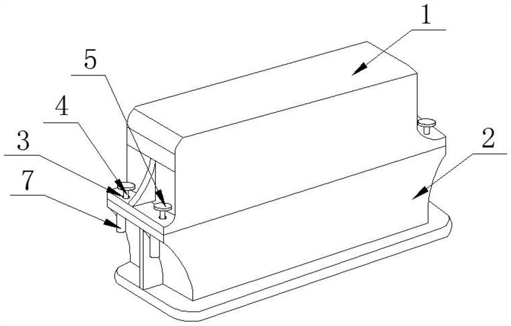
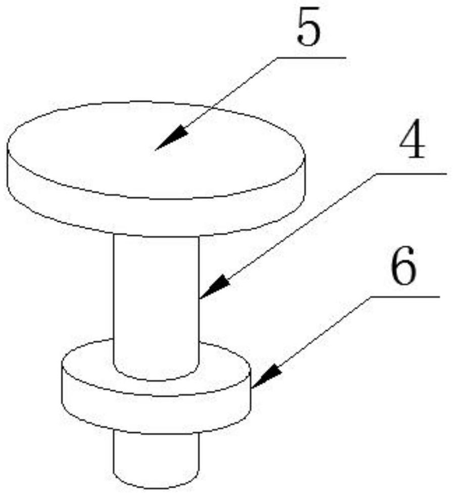
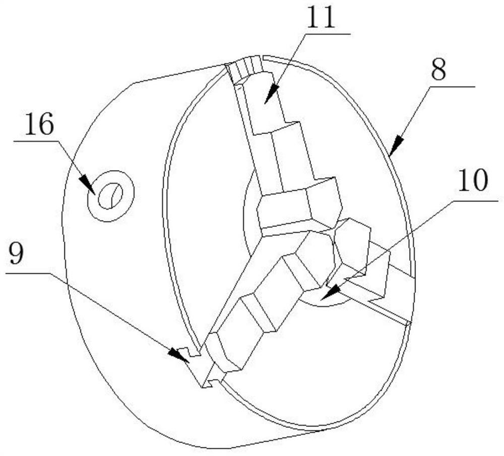
[0024] Such as Figure 1-4 As shown, a worm gear reducer that is easy to maintain and replace according to an embodiment of the present invention includes a box body, and the box body is composed of a casing one 1 and a casing two 2, and the two ends of the casing one 1 are respectively A fixed hole 3 is arranged symmetrically, and a movable rod 4 is penetrated in the fixed hole 3, and the top of the movable rod 4 is connected with the draw ring 5, and a snap ring 6 is sleeved on the bottom of the movable rod 4. The housing two 2 is provided with a fixing assembly 7 adapted to the snap ring 6, the fixing assembly 7 includes a protective cover 8, and the protective cover 8 is connected to the outer wall of the housing two 2, and the protective The cover 8 is provided with several evenly distributed limiting grooves 9, the limiting grooves 9 are close to one end and are provided with a card slot 10 in the middle of the protective cover 8, and the limiting grooves 9 are respectiv...

Embodiment 2

[0027] Such as Figure 4-6 As shown, the deceleration assembly includes a rotating shaft 17, a worm 18 is sleeved on the rotating shaft 17, one end of the rotating shaft 17 extends to the box, and the other end of the rotating shaft 17 runs through the Described box body and extend to its outside, one side of described worm 18 is provided with the worm wheel 19 that meshes with it, and the wheel shaft of described worm wheel 19 is connected with described box inner wall, is sleeved on the wheel shaft of described worm wheel 19 Gear one 20, one side of the gear one 20 is provided with a gear two 21 meshing with it, the gear shafts of the gear two 21 are all connected with the inner wall of the box, and the gear shafts of the gear two 21 are sleeved There is a gear three 22, one side of the gear three 22 is provided with a gear four 23 meshing with it, the gear shaft at one end of the gear four 23 extends to the inner wall of the box, and the gear at the other end of the gear fo...


PUM


Abstract

The invention discloses a worm gear reducer convenient to maintain and replace. The worm gear reducer comprises a box body, the box body is composed of a first shell and a second shell, fixing holes are symmetrically formed in the two ends of the first shell correspondingly, movable rods are arranged in the fixing holes in a penetrating manner, the top ends of the movable rods are connected with pull rings, and the bottoms of the movable rods are sleeved with clamping rings in a clamped manner; fixing assemblies matched with the clamping rings are arranged on the second shell, each fixing assembly comprises a protective cover, the protective covers are connected with the outer wall of the second shell, a plurality of evenly-distributed limiting grooves are formed in each protective cover,and clamping grooves are formed in the ends, close to each other, of the limiting grooves and located in the middles of the protective covers; and clamping jaws matched with the limiting grooves are arranged in the limiting grooves in a sleeved manner correspondingly, and racks are arranged at the bottom ends of the clamping jaws correspondingly. The worm gear reducer has the beneficial effects that the overall design is reasonable, speed reduction of the device can be achieved, and the reducer is convenient to disassemble and maintain.

Description

technical field [0001] The invention relates to the field of reducers, in particular to a worm gear reducer which is easy to maintain and replace. Background technique [0002] The worm gear reducer is a power transmission mechanism that uses the speed converter of the gear to reduce the number of revolutions of the motor to the desired number of revolutions and obtain a larger torque mechanism. It is mainly composed of transmission parts worm gear, shaft, bearing, Composed of the box and its accessories, the main function of the worm gear is to transmit the motion and power between the two interlaced shafts, and the main function of the bearing and the shaft is to transmit power, operate and improve efficiency. Most of the existing worm gear reducers are not easy to disassemble, which makes the maintenance and replacement of the reducer more troublesome, and makes the use of the reducer have certain limitations. [0003] Aiming at the problems in the related technologies, ...

Claims


Application Information

Patent Timeline
Patent Type & Authority Applications(China)
IPC IPC(8): F16H57/02F16H57/023F16H57/038F16H57/039
CPCF16H57/02F16H57/023F16H57/038F16H57/039F16H2057/0235
Inventor 许春燕
Owner 许春燕
Learn More