Supercharge Your Innovation With Domain-Expert AI Agents!

Efficient and energy-saving adjustable hot-blast stove

A high-efficiency, energy-saving, adjustable technology, applied in the direction of air heaters, fluid heaters, heat exchange equipment, etc., can solve the problems of heat loss in hot air pipes, energy waste, lack of insulation structures, etc., to increase the footprint area and stabilize Support and enhance the effect of supporting and stabilizing the shape

Pending Publication Date: 2020-12-08
天津征鑫热能设备制造有限公司
View PDF1 Cites 0 Cited by
  • Summary
  • Abstract
  • Description
  • Claims
  • Application Information

AI Technical Summary

Problems solved by technology

[0004] 1. When the hot air pipe of the negative pressure adjustable high-efficiency energy-saving hot air stove in the prior art is used for hot air transportation, the outside of the hot air pipe lacks an effective heat preservation structure, which leads to heat loss at the hot air pipe, thereby affecting the temperature of the hot air delivery. At this time, it is necessary to increase the amount of fuel burned in the furnace body to gradually increase the temperature of the conveying hot air, resulting in energy waste. Therefore, we propose a high-efficiency and energy-saving adjustable hot air stove
[0005] 2. The bottom of the negative pressure adjustable high-efficiency energy-saving hot blast stove in the prior art has a simple foot that touches the ground for support, but the contact area between the foot and the ground is small, and it cannot handle the hot air well under the furnace body. Furnace for support, for this reason, we propose a high-efficiency energy-saving adjustable hot blast stove

Method used


Image

  • Efficient and energy-saving adjustable hot-blast stove
  • Efficient and energy-saving adjustable hot-blast stove
  • Efficient and energy-saving adjustable hot-blast stove

Examples


Embodiment Construction

[0020] In order to make the purpose, technical solutions and advantages of the present invention clearer, the present invention will be further described in detail below in conjunction with the accompanying drawings. Obviously, the described embodiments are only some of the embodiments of the present invention, rather than all of them. Based on the embodiments of the present invention, all other embodiments obtained by persons of ordinary skill in the art without making creative efforts belong to the protection scope of the present invention.

[0021] The following will combine Figure 1 ~ Figure 3 A high-efficiency and energy-saving adjustable hot blast stove according to an embodiment of the present invention will be described in detail.

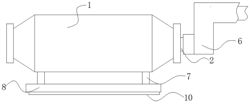
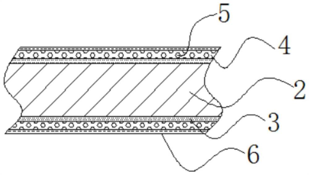
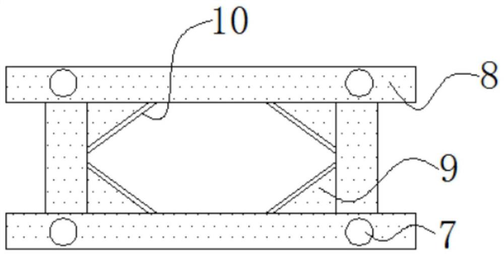
[0022] refer to Figure 1-3 As shown, a high-efficiency and energy-saving adjustable hot blast stove provided by the embodiment of the present invention includes a furnace body 1, a hot air pipe 2 protrudes from one end of the furnace bod...


PUM


Abstract

The invention discloses an efficient and energy-saving adjustable hot-blast stove and belongs to the technical field of hot-blast stoves. The hot-blast stove comprises a stove body. A hot air pipe extends out of one end of the stove body. A ceramic fiber sleeve is connected to the outer side of the hot air pipe in a sleeving manner. A rubber sleeve is connected to the outer side of the ceramic fiber sleeve in a sleeving manner. An inner hole is formed in the rubber sleeve. A glass cotton sleeve is connected to the outer side of the rubber sleeve in a sleeving manner. Bottom feet extend out ofthe bottom ends of the stove body. A parallel bottom frame is welded to the bottom ends of the bottom feet. A triangular inner plate is welded to an inner corner of the parallel bottom frame. The ceramic fiber sleeve, the rubber sleeve and the glass cotton sleeve are sequentially arranged on the outer side of the hot air pipe on one side of the stove body. The ceramic fiber sleeve, the rubber sleeve and the glass cotton sleeve form a composite multi-layer heat preservation structure to preserve heat of the outer side of the hot air pipe, moreover, the inner hole of the rubber sleeve can form avacuum heat insulating structure, and output temperature of the hot air pipe is effectively protected against running off to the outside.

Description

technical field [0001] The invention relates to the technical field of hot blast stoves, in particular to an adjustable hot blast stove with high efficiency and energy saving. Background technique [0002] The hot blast stove is a thermal power machine, which was widely used in our country in the late 1970s. It has become a replacement product for electric heat sources and traditional steam power heat sources in many industries. There are many varieties and complete series of hot blast stoves, which are divided into two types: hand-fired and machine-fired according to the way of coal feeding, and divided into coal, oil, and gas stoves according to the type of fuel. [0003] Patent No. CN94227577.2 is a negative pressure adjustable high-efficiency energy-saving hot air stove, which is composed of a furnace body, an air inlet device, a chimney, a smoking machine, and a hot air pipe. It is characterized in that the combustion chamber is a bottleneck structure with unequal secti...

Claims


Application Information

Patent Timeline
Patent Type & Authority Applications(China)
IPC IPC(8): F24H3/00F24H9/00F24H9/06F16L59/02F16L59/065F16L59/14
CPCF16L59/029F16L59/065F16L59/14F24H3/00F24H9/0052F24H9/06
Inventor 陈文顺
Owner 天津征鑫热能设备制造有限公司
Features
  • R&D
  • Intellectual Property
  • Life Sciences
  • Materials
  • Tech Scout
  • Unparalleled Data Quality
  • Higher Quality Content
  • 60% Fewer Hallucinations
Learn More