Triple-effect heat recovery type mixed-air type heat pump drying system and application thereof
A heat pump drying and heat recovery technology, applied in heat recovery systems, drying, heat pumps, etc., can solve the problem of insufficient heat recovery, unrecovered cold energy loss, and inability to reheat to normal return air temperature (phase change temperature requires Lower than the return air temperature and other issues, to achieve the effect of low inlet air temperature, improved dehumidification energy efficiency, and improved energy utilization
- Summary
- Abstract
- Description
- Claims
- Application Information
AI Technical Summary
Problems solved by technology
Method used
Image

Examples
Example Embodiment
[0050] Example 1
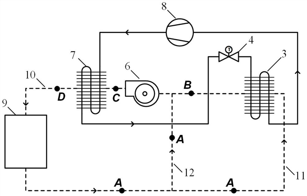
[0051] In this embodiment, the three-effect heat recovery type mixed air heat pump drying system (see image 3 ), including loop heat pipe, refrigerant cycle and air cycle.
[0052] The loop heat pipe includes the refrigerant channel of the precooler 1 and the refrigerant channel of the reheater 2 which are connected in circulation. The precooler 1 and the reheater 2 are connected, and refrigerant flows inside. The flow of refrigerant between precooler 1 and reheater 2 is driven by gravity / capillary forces or pumps, depending on the type of heat pipes used in the implementation.
[0053] The refrigerant cycle includes the refrigerant channel of the evaporator 3, the compressor 8, the refrigerant channel of the condenser 7, the refrigerant channel of the subcooling reheat coil 5, and the throttling element 4, which are connected in sequence. It is connected with the refrigerant channel of the evaporator 3 to form a cycle.
[0054] In the refrigerant cycle...
Example Embodiment
[0061] Example 2
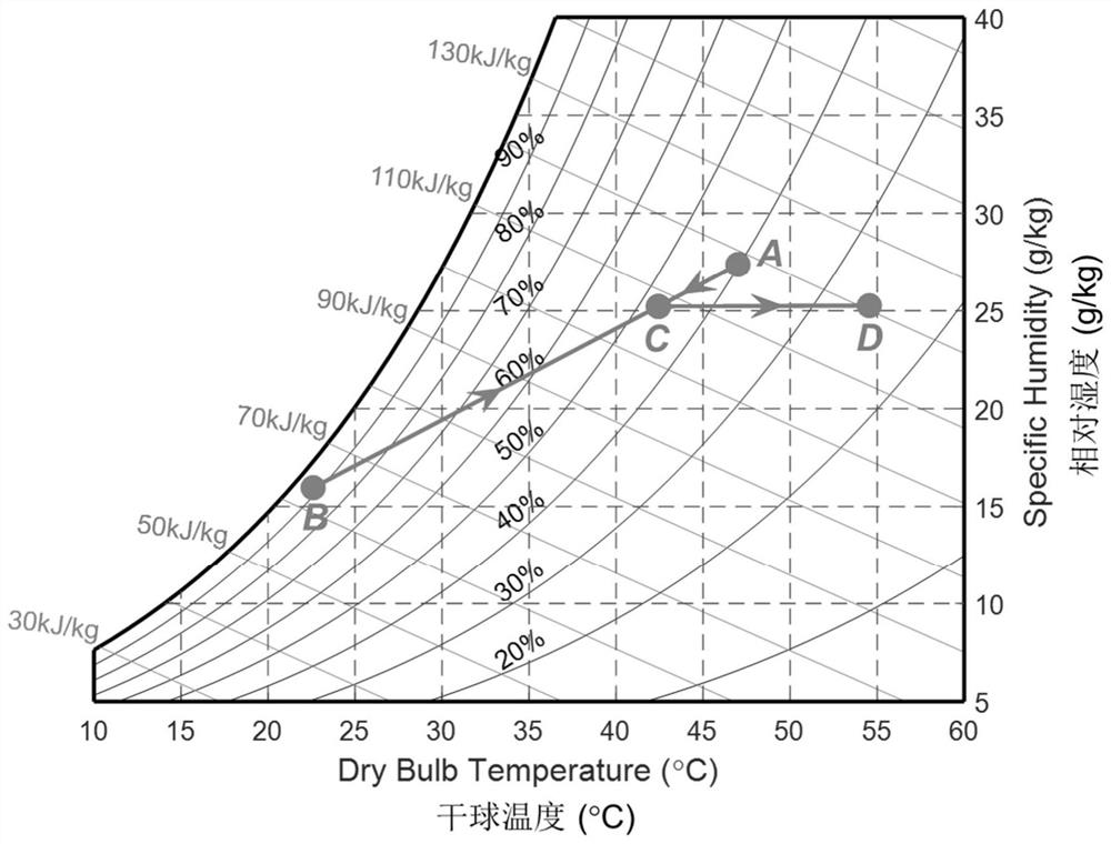
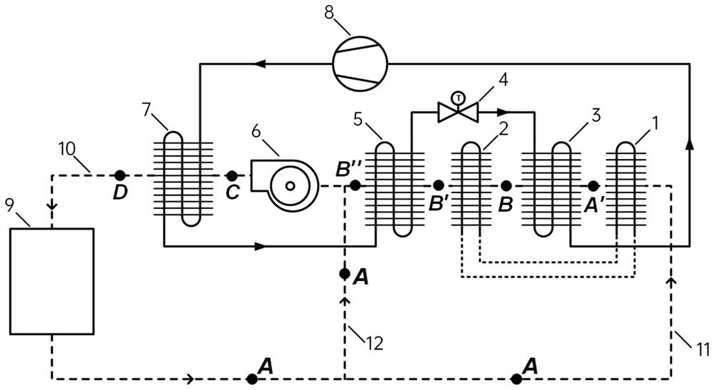
[0062] This embodiment also adopts the three-effect heat recovery of loop heat pipe, evaporator and subcooling reheating coil. Figure 5 , Image 6 shown. In the first return air passage 11, the air flows through the loop heat pipe precooler 1 to cool down and the evaporator 3 to cool and dehumidify (state A→A'→B) in sequence, and then flows through the cold reheat coil 5 and the loop heat pipe The reheater 2 reheats to the normal return air temperature (state B→B"→B').
[0063] Compared with Embodiment 1, only the sequence of the loop heat pipe reheater 2 and the supercooling reheat coil 5 along the air flow path is different, and the loop heat pipe reheater 2 is arranged behind the supercooling reheat coil 5 . In this embodiment, the deep recovery of cold energy by the subcooling and reheating coil 5 is prioritized, and the functions of the loop heat pipe and the subcooling and reheating coil are not changed.
Example Embodiment
[0064] Example 3
[0065] This embodiment adopts the three-effect heat recovery of the loop heat pipe, evaporator and subcooling reheating coil, wherein the subcooling reheating coil is provided with a first-level subcooling reheating coil 5-1 and a second-level subcooling reheating coil The two-stage deep cooling energy recovery of pipe 5-2, the system schematic diagram and the psychrometric diagram of the air condition are as follows Figure 7 , Figure 8 shown. In the first return air channel 11, the air flows through the loop heat pipe precooler 1 to cool down and the evaporator 3 to cool and dehumidify (state A→A'→B), and the low-temperature return air after the evaporator 3 passes through the first stage in sequence. The cold energy recovery of the cold reheating coil 5-1, the loop heat pipe reheater 2 and the secondary subcooling reheating coil 5-2 (state B→B1”→B’→B2”) is reheated to Normal return air temperature.
[0066] Compared with Embodiment 1, the first-stage...
PUM
 Abstract
Description
Claims
Application Information
 - R&D Engineer
- R&D Manager
- IP Professional
- Industry Leading Data Capabilities
- Powerful AI technology
- Patent DNA Extraction
Browse by: Latest US Patents, China's latest patents, Technical Efficacy Thesaurus, Application Domain, Technology Topic.
© 2024 PatSnap. All rights reserved.Legal|Privacy policy|Modern Slavery Act Transparency Statement|Sitemap