
Ultrasonic gas flow measuring device

A gas flow and measuring device technology, applied in the field of ultrasonic measurement, can solve the problems of increasing the difficulty of flow algorithm of metering software, affecting metering stability and metering accuracy, causing eddy current, turbulent flow, laminar flow, etc., and achieving good uniformity and laminar flow. Symmetry, improving stability and metering accuracy, reducing the effect of eddy currents

Pending Publication Date: 2020-12-08
QINGDAO IESLAB ELECTRONICS CO LTD
View PDF0 Cites 0 Cited by
  • Summary
  • Abstract
  • Description
  • Claims
  • Application Information

AI Technical Summary

Problems solved by technology

Due to the limitation of the structural size of the ultrasonic gas meter or ultrasonic flowmeter, after the gas enters the chamber of the meter, incident impact, reflection of the cavity wall and components will occur, and after the mixing process of incident and reflection, it will cause Phenomena such as eddy current, turbulent flow, laminar flow, etc., and poor airflow uniformity increase the difficulty of the flow algorithm of the metering software and affect the stability and accuracy of metering, especially in the case of large flow rates. more prominent
In addition, the density distribution law of the airflow in the flow measurement pipeline of the existing ultrasonic gas meter or ultrasonic flowmeter is: the middle layer is the densest, and as the distance away from the middle layer increases, the airflow density will continue to decrease. The airflow density is the lowest, that is, the laminar flow distribution is formed. Due to the limitation of the structure, the laminar flow symmetry is usually not good, which also increases the difficulty of the flow algorithm of the measurement software and affects the measurement accuracy.

Method used


Image

  • Ultrasonic gas flow measuring device
  • Ultrasonic gas flow measuring device
  • Ultrasonic gas flow measuring device

Examples


Embodiment Construction

[0029] The present invention will be further described below in conjunction with accompanying drawing by non-limiting embodiment:

[0030] as attached Figure 4 Shown is a schematic diagram of the internal structure of an ultrasonic gas meter or an ultrasonic flowmeter, which mainly includes a housing 14 on which an air inlet 1 and an air outlet 15 are arranged, and an ultrasonic flow measuring tube is arranged inside the housing 14 Road 6, the front end of the ultrasonic flow measurement pipeline 6 is the inlet 5 of the ultrasonic flow measurement pipeline, and the ultrasonic flow measurement pipeline 6 is provided with an ultrasonic upstream transducer 7, an ultrasonic downstream transducer 8, a pressure sensor 9, and a temperature sensor 10. PCB 11 , the back end of the ultrasonic flow measurement pipeline 6 is connected with a gas outlet elbow 12 and a valve body 13 , and the valve body 13 is connected with the gas outlet 15 on the casing 14 . The above settings in this e...


PUM


Abstract

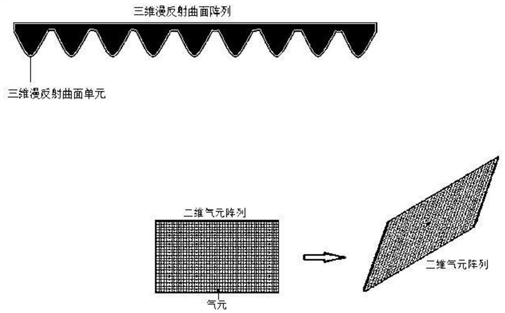
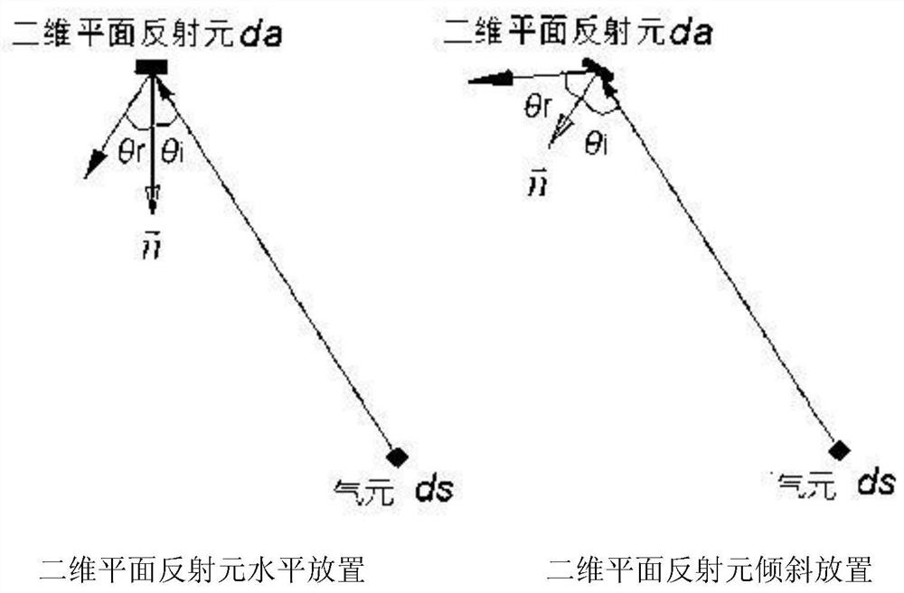
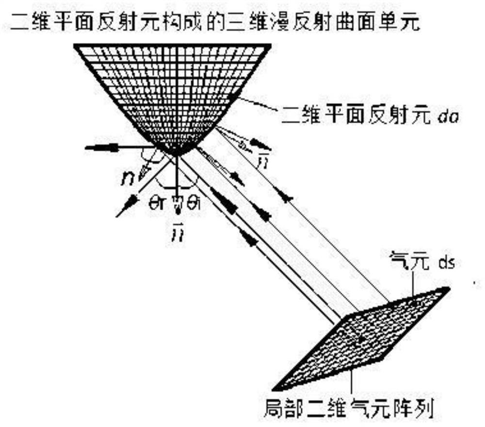
The invention discloses an ultrasonic gas flow measuring device. The ultrasonic flowmeter comprises a shell, an air inlet and an air outlet are formed in the shell, an ultrasonic flow measuring pipeline is arranged in the shell, and the ultrasonic flowmeter is characterized in that an air flow diffuse reflection device is further arranged in the shell and comprises an air flow three-dimensional diffuse reflection structure and an air flow guide structure; the airflow three-dimensional diffuse reflection structure is formed by a plurality of three-dimensional diffuse reflection curved surface unit arrays, the surfaces of the three-dimensional diffuse reflection curved surface units form airflow three-dimensional diffuse reflection curved surfaces, the airflow guide structure is connected with an air inlet in the shell, and the airflow guide structure is provided with an air outlet. A certain distance is formed between two-dimensional aperture surface of air outlet of airflow guide structure and airflow three-dimensional diffuse reflection curved surface of airflow three-dimensional diffuse reflection structure, and certain included angle is formed between two-dimensional aperture surface of air outlet of airflow guide structure and airflow three-dimensional diffuse reflection curved surface of airflow three-dimensional diffuse reflection structure, so that airflow flowing out ofair outlet of airflow guide structure can be sprayed to airflow three-dimensional diffuse reflection curved surface.

Description

technical field [0001] The invention relates to an ultrasonic gas flow measuring device, which belongs to the technical field of ultrasonic measurement. Background technique [0002] Ultrasonic gas meter or ultrasonic flow meter is a kind of ultrasonic gas flow measurement device widely used at present. Due to the limitation of the structural size of the ultrasonic gas meter or ultrasonic flowmeter, after the gas enters the chamber of the meter, incident impact, reflection of the cavity wall and components will occur, and after the mixing process of incident and reflection, it will cause Phenomena such as eddy current, turbulent flow, laminar flow, etc., and poor airflow uniformity increase the difficulty of the flow algorithm of the metering software and affect the stability and accuracy of metering, especially in the case of large flow rates. more prominent. In addition, the density distribution law of the airflow in the flow measurement pipeline of the existing ultrason...

Claims


Application Information

Patent Timeline
Patent Type & Authority Applications(China)
IPC IPC(8): G01F1/66G01F15/00G01F15/14
CPCG01F1/662G01F15/00G01F15/14
Inventor 于强刘立国胡学斌
Owner QINGDAO IESLAB ELECTRONICS CO LTD
Learn More